|
|
~MENU~ |
| Home |
| The Concept |
| The Boat |
| Bringing Her Home |
|
Weekly Progress Log |
|
Daysailor Projects |
| The Boat Barn |
| Resources |
| Other Sites |
| Email Tim |
|
|
| Progress Report: 2004 Archives |
|
January February March April May June July August September October November December |
|
Reports from March 2004 3/7/04 3/14/04 3/21/04 3/28/04 Log for the Week Ending March 7, 2004 Again, the week got off to a slow start, as I had other things to attend to. But I still managed to continue working on the short deck beam glue-ups. I found that the resorcinol glue was taking too long to cure sufficiently in the 60° shop. Granted, the molding station is located at the coldest part of the shop, so it was probably even cooler than that. To ensure that the molded beams would hold their shape and stay glued, I had to leave the pieces in the clamps for more than a day. Too long. Keeping the shop temperature higher than 60 not only makes working on the boat uncomfortably warm, but also costs too much to do so on a consistent basis. I switched back to using epoxy, since I find that it always cures sufficiently in 24 or fewer hours (usually just overnight), even at the lower shop temperatures.
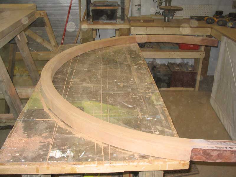
Click here to read more about the forward cabin trunk carlin layout. |
 I
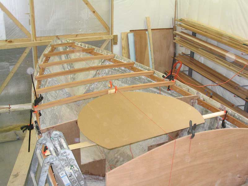
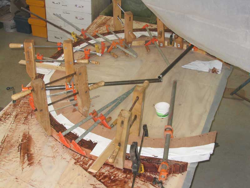
continued on Wednesday by securing the round mold to a sheet of plywood and
covering both parts in plastic, in preparation for laminating. Then I
milled and glued up the nine thin boards required to make the assembly, a task
challenging enough that for a time I wondered if I was going to fail to get the
pieces clamped in time. I
continued on Wednesday by securing the round mold to a sheet of plywood and
covering both parts in plastic, in preparation for laminating. Then I
milled and glued up the nine thin boards required to make the assembly, a task
challenging enough that for a time I wondered if I was going to fail to get the
pieces clamped in time.
|
 In
the end, I succeeded, and after a couple days curing in the clamps, I removed
the new laminated assembly and was pleased with the final result. As of
this writing, the piece still needs to be cleaned up, sanded, and cut to final
size, but that will happen next week. In
the end, I succeeded, and after a couple days curing in the clamps, I removed
the new laminated assembly and was pleased with the final result. As of
this writing, the piece still needs to be cleaned up, sanded, and cut to final
size, but that will happen next week.
|
|
Log for the Week Ending March 14, 2004
|
 I
began Monday morning with the laminated carlin. The first task at hand was
to remove the excess glue and smooth the piece. My belt sander died last
week, so I used a borrowed power plane (handheld) to remove the bulk of the glue
and help smooth both sides of the lamination. I started to get some
tearout, so I switched to my trusty Porter Cable DA to finish cleaning up the
piece. When I had finished, I temporarily installed it up in the boat with
clamps so that I could work on the next step: determining where the
cockpit/cabin carlins would naturally join into the curved piece. I
began Monday morning with the laminated carlin. The first task at hand was
to remove the excess glue and smooth the piece. My belt sander died last
week, so I used a borrowed power plane (handheld) to remove the bulk of the glue
and help smooth both sides of the lamination. I started to get some
tearout, so I switched to my trusty Porter Cable DA to finish cleaning up the
piece. When I had finished, I temporarily installed it up in the boat with
clamps so that I could work on the next step: determining where the
cockpit/cabin carlins would naturally join into the curved piece.
|
|
I spent about 5 hours on Tuesday planing more rough stock down to 3/4" thickness and milling all the lumber required to complete the deck frame. I needed to mill pieces for the carlins, each of which will be about 15' long and made up of three pieces of stock laminated together, and to mill enough pieces to make up the required number of short deck beams (26 total, or 13 pair) and the aftermost two full-width beans (2). Planing and milling these various pieces, plus cleanup of the shop afterwards, was the bulk of the work completed on this day, but now at least I have all the pieces cut, which should streamline my operations for a time. I used up virtually all my remaining mahogany, so I'll need to order more when it comes time for additional structure and, eventually, trim. But I certainly have plenty to do in the meantime.
|
|
With the milling out of the way, I continued by preparing to work on the cockpit carlins. My first step was to cut out slots large enough for the carlins in the midships and after bulkheads, which took a few minutes with a jigsaw. Then I trial fit the sections on one side, just to see how things might go. It became immediately clear that the curved forward piece would have to be securely installed to ensure the proper fit with the sides, so I put aside the carlin pieces and prepared to permanently install the last full-width deck beam, which is located just forward of (and tangent to) the curved carlin. I'd have to permanently install this beam before the carlin, since the carlin relies on the beam for support, in part. |
|
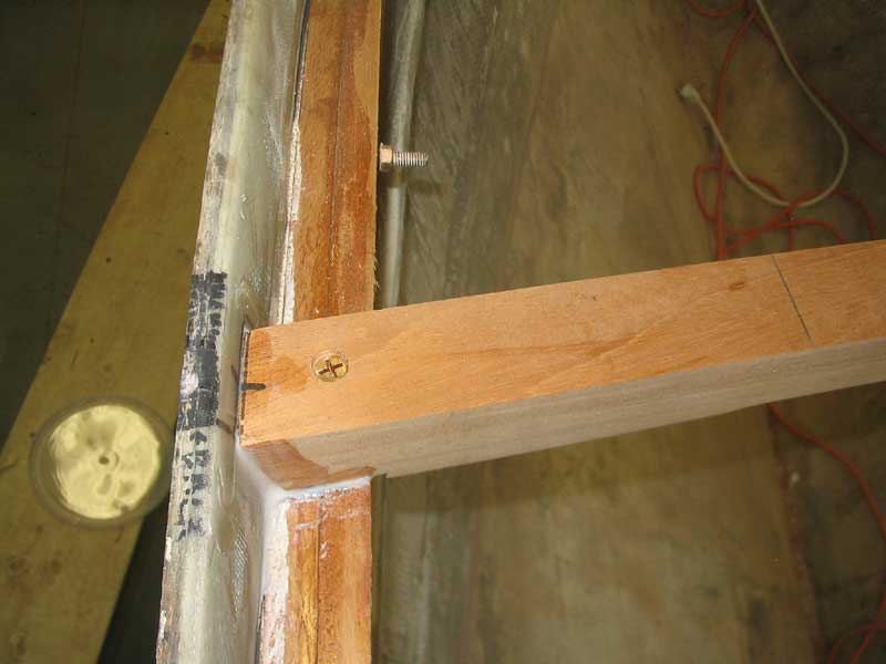
With the beam sanded, I permanently installed it in the boat. I secured it to the sheer clamp with some thickened epoxy in the joint between the beam end and the hull, plus a bronze #14 x 3" screw at each end. |
 To
protect the beam, I applied a quick sealer coat of varnish thinned about 50%
with thinner, which will prevent fingerprints and dirt from sullying the clean,
sanded beam. Eventually, I'll apply several more coats of varnish to this
and all the beams (once installed), so that the varnishing is complete before
the deck is laid. To
protect the beam, I applied a quick sealer coat of varnish thinned about 50%
with thinner, which will prevent fingerprints and dirt from sullying the clean,
sanded beam. Eventually, I'll apply several more coats of varnish to this
and all the beams (once installed), so that the varnishing is complete before
the deck is laid.
Look for more details on the deck beam installation later on, once I start installing all the beams. For now, I stopped at just the one beam that was required in order to complete other framing steps. In a couple days, I'll install the first fill-width beam aft of the cockpit (to which the after end of the carlin will attach), but first I had to laminate up that beam section. With two short beams in the mold, I had to wait till Wednesday. |
 Wednesday, I glued up the beam first thing, then
moved on to other tasks. There was plenty to do. My first step for
the day was to prepare to install the curved carlin permanently. I
installed for good with bronze bolts, screws, and thickened epoxy, then
continued working by beginning the construction of the cockpit carlins. Wednesday, I glued up the beam first thing, then
moved on to other tasks. There was plenty to do. My first step for
the day was to prepare to install the curved carlin permanently. I
installed for good with bronze bolts, screws, and thickened epoxy, then
continued working by beginning the construction of the cockpit carlins.
|
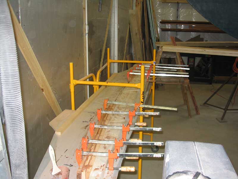
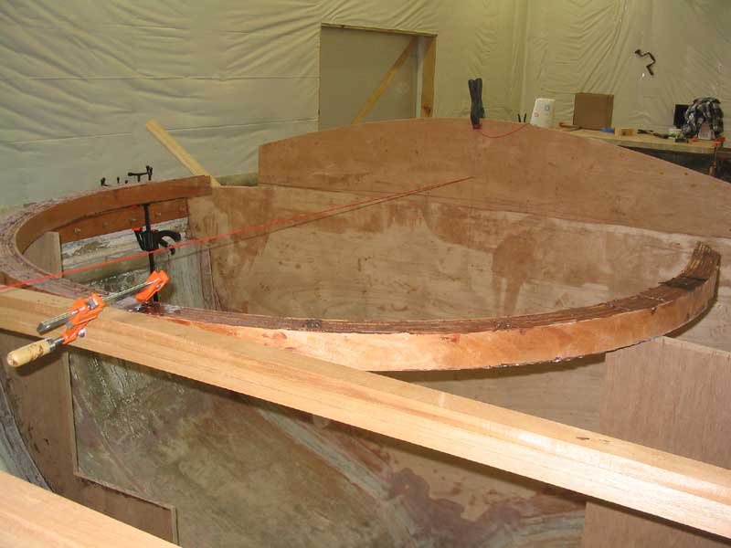
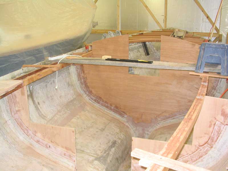
 During
the rest of Wednesday, Thursday, and Friday morning, I built the cockpit carlins
on each side. These carlins, which define the shape and edges of the
cockpit, cabin trunk, and sidedecks, are built of three thicknesses of mahogany,
glued together with resorcinol glue. By noon on Friday, both carlins were
permanently installed, and the boat had started to really take shape and show
off a hint of her final appearance. During
the rest of Wednesday, Thursday, and Friday morning, I built the cockpit carlins
on each side. These carlins, which define the shape and edges of the
cockpit, cabin trunk, and sidedecks, are built of three thicknesses of mahogany,
glued together with resorcinol glue. By noon on Friday, both carlins were
permanently installed, and the boat had started to really take shape and show
off a hint of her final appearance.
Click here to read about building and installing the cockpit carlins. |
|
With that, I took Friday afternoon and Saturday off, feeling like I had accomplished a significant amount of work during the week. What's coming up next? Dressing the
carlins, some busy work and undesirable chores like cutting off sheer clamp
boltheads, epoxy filleting and glasswork and the like, and beginning to fit and
permanently install all the short deck beams. Of course I'll continue
gluing up two short beams per day until they're all done. As of this
writing, I have 6 or 7 days' worth of glueups remaining. |
|
Log for the Week Ending March 21, 2004
|
|
|
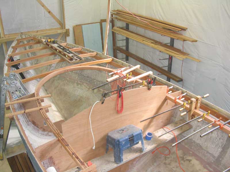
 I also made the plunge and cut out the midships
bulkhead in way of the companionway hatch. I made the opening narrower and
shorter than the final cut will require, but with the cutout I hoped it would
make it easier to get around inside the boat, since before cutting I had to
climb in and out of the boat on each side of the bulkhead, as there was no
access through the full-width piece. Besides, with the pending
installation of deck beams and other related work, the ladder I had rigged on
the forward side of the boat would start to get in the way, so it was time for
me to create other access into the boat. I also made the plunge and cut out the midships
bulkhead in way of the companionway hatch. I made the opening narrower and
shorter than the final cut will require, but with the cutout I hoped it would
make it easier to get around inside the boat, since before cutting I had to
climb in and out of the boat on each side of the bulkhead, as there was no
access through the full-width piece. Besides, with the pending
installation of deck beams and other related work, the ladder I had rigged on
the forward side of the boat would start to get in the way, so it was time for
me to create other access into the boat.
|
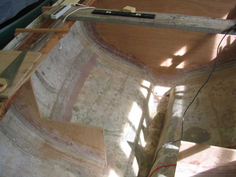
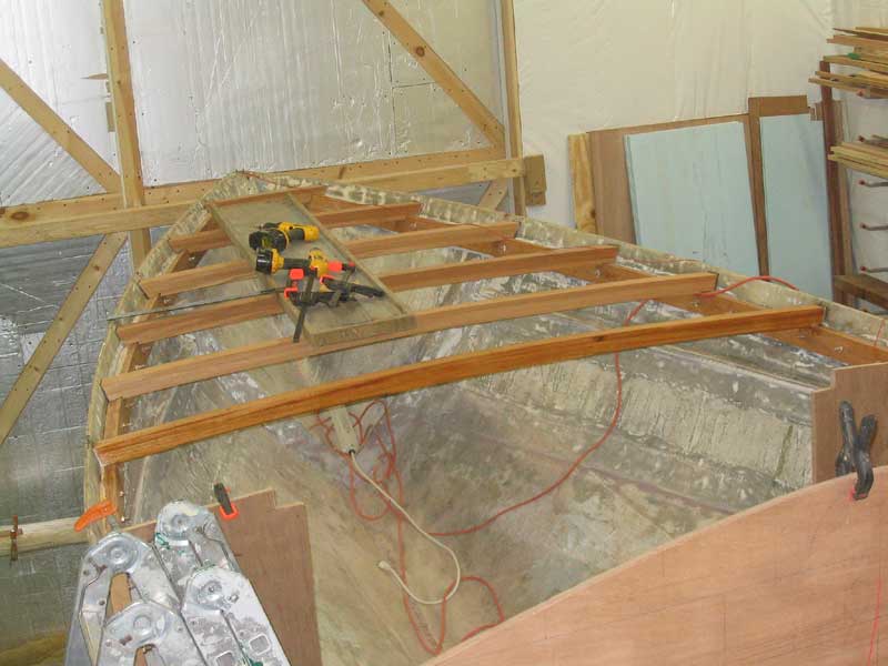
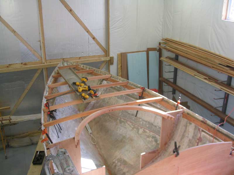
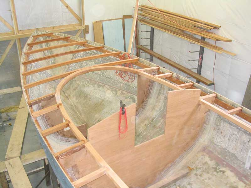 I spent most of the week working on installing deck
beams, in particular the short beams running
between the hull and carlins on each side. There are 22 of these beams in
total (I overestimated earlier when I said 26). Installing the beams
required first dressing off the carlins to reflect the approximate camber of the
deck, and then cutting angled mortises at each beam location along the
carlins. Then, I could fit each beam in turn, using the same marking
methods as I used when fitting the full-width foredeck beams. At the same
time, I took care of the chore of cutting off the excess bolts protruding
through the sheer clamp. I used my angle grinder fitted with a cutoff
wheel to remove the excess. By Friday morning, all the deck beams were in
and secured, completing the deck framing. I spent most of the week working on installing deck
beams, in particular the short beams running
between the hull and carlins on each side. There are 22 of these beams in
total (I overestimated earlier when I said 26). Installing the beams
required first dressing off the carlins to reflect the approximate camber of the
deck, and then cutting angled mortises at each beam location along the
carlins. Then, I could fit each beam in turn, using the same marking
methods as I used when fitting the full-width foredeck beams. At the same
time, I took care of the chore of cutting off the excess bolts protruding
through the sheer clamp. I used my angle grinder fitted with a cutoff
wheel to remove the excess. By Friday morning, all the deck beams were in
and secured, completing the deck framing.
Click here to read about installing the deck beams in detail. |
|
Log for the Week Ending March 28, 2004 I had so much going on during the week that I found it tough to get out and put in solid days of work on the boat. Besides, with the deck frame essentially done, this week marked a transitional zone in the scope of the project, and I often find it a little tough to shift gears when one major project is completed. However, by the end of the week I had gotten past those difficulties, and, other than increasingly less time to spend working (as a result of other demands on my time now that spring is arriving), I managed to get started on a few more important steps in the overall process. Before I think about putting on the deck sheathing, I wanted to ensure that I didn't close myself in too early, and regret it later. Even with the deck framing in place, I can still stand up between the frames as necessary, so it makes working on the hull and interior easier than it would be with the sheathing applied. Therefore, I decided to concentrate on some smallish, but important nonetheless, tasks that, when completed, would allow me to continue with deck sheathing in a timely manner. |
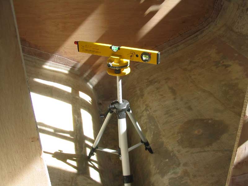
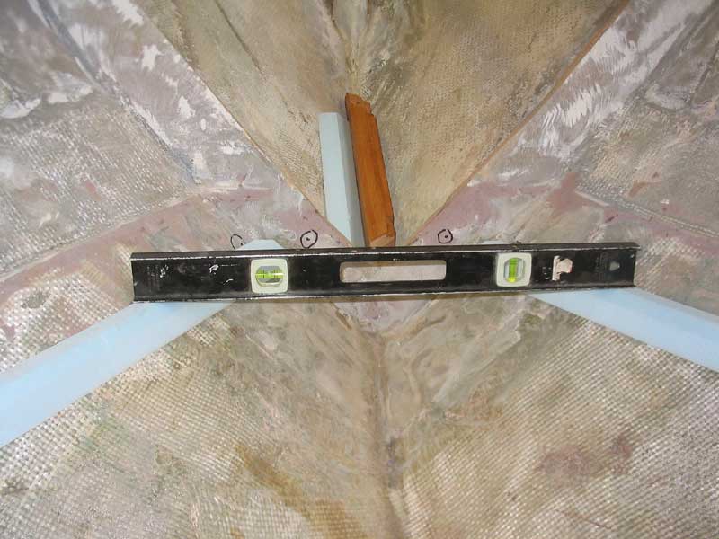 I began in the forward part of the boat, which will
become the interior accommodations space, such as it is. The first item on
my agenda was to install some basic structural support for the eventual vee
berth, forward of the bulkhead. Earlier, during the installation of the
bulkhead, I had determined the height of the vee verth platform, and, using that
as a guide, I used my laser level to mark out level points on the hull on each
side, forward of the bulkhead. I began in the forward part of the boat, which will
become the interior accommodations space, such as it is. The first item on
my agenda was to install some basic structural support for the eventual vee
berth, forward of the bulkhead. Earlier, during the installation of the
bulkhead, I had determined the height of the vee verth platform, and, using that
as a guide, I used my laser level to mark out level points on the hull on each
side, forward of the bulkhead.
|
 I
also marked out the basic height of the cabin sole on the hull, and made
preparations to fabricate and install some floors (cabin sole supports) beneath
that level, on which the plywood cabin sole substrate would be installed. I
also marked out the basic height of the cabin sole on the hull, and made
preparations to fabricate and install some floors (cabin sole supports) beneath
that level, on which the plywood cabin sole substrate would be installed.
|
|
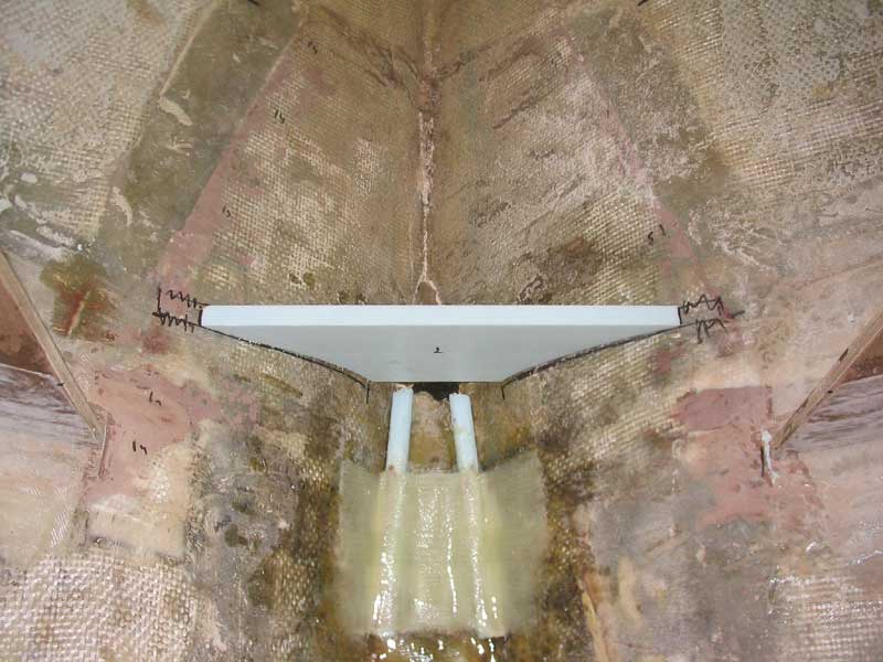
While all the rest of this was ongoing, I began the construction of the new mast step. Since the boat currently has no rig, I decided to build a keel-stepped mast support, rather than deck-stepped as the Triton had originally. When the time comes to order a new mast, I'll simply add whatever length to the section as is necessary to keep the masthead at the same height above the water. Follow this link to see how I started building the mast step. |