|
|
~MENU~ |
| Home |
| The Concept |
| The Boat |
| Bringing Her Home |
|
Weekly Progress Log |
|
Daysailor Projects |
| The Boat Barn |
| Resources |
| Other Sites |
| Email Tim |
|
|
|
From a Bare Hull: Deckbeams (Page 2) |
|
|
|
|
|
|
|
|
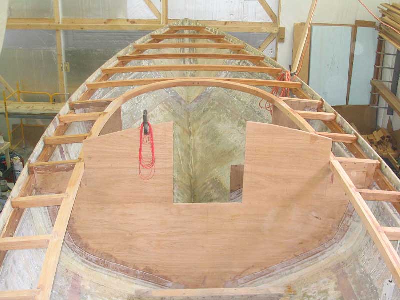
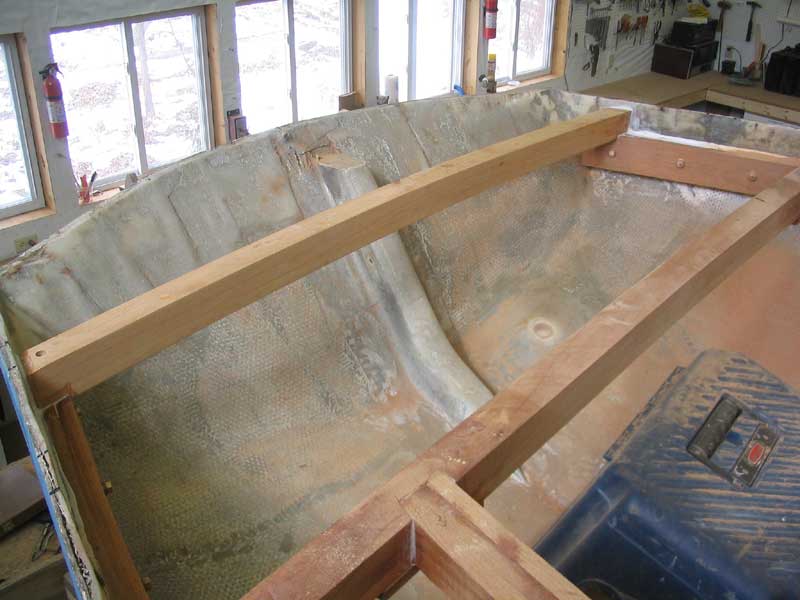 couple days later, I installed a second full-width beam 16" aft of the
one demarking the end of the cockpit, completing the framing in that area.
couple days later, I installed a second full-width beam 16" aft of the
one demarking the end of the cockpit, completing the framing in that area.
|
|
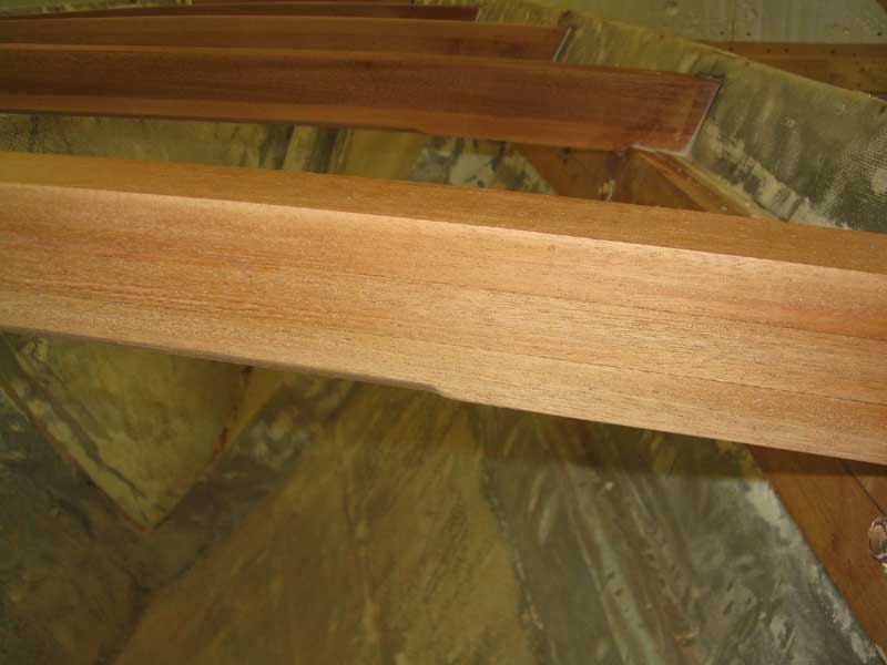
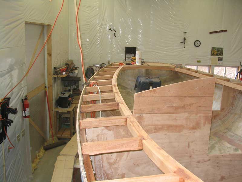
Short Deck Beams: Fitting and Installation With the longitudinal carlins installed permanently, running from the curved piece at the forward end of the eventual cabin trunk to the aft end of the cockpit, I was ready to install the short deck beams running between the hull (supported by the sheer clamp) and the carlin. For several weeks, I had been laminating the required beams, so I had a stockpile of nearly enough to complete the job. I began at the planer, where I smoothed both sides of all the beams to remove excess glue and to clean up the wood, as well as to make all the beams a consistent thickness. During the sheer clamp installation, I had more or less marked out all the beam locations, but I took several minutes to double check the locations and make minor adjustments as needed. I did find a few places where the spacing ended up differently than I had initially expected, mainly because of the after cockpit edge (beam), since at the initial layout I had not yet known its location. In general, with one or two exceptions, the beam spacing remained consistent throughout the entire length of the boat, at 18" on center (16" between beams). |
|
Next, I had to address the glued-up carlins. Before installing the beams, I dressed off the top edge of the carlin to approximate the deck camber. I found a belt sander was the best tool for this operation, as using a plane on the rough surface and over all the glue spillout was difficult and unsatisfactory. Fortunately, the process was not difficult with the sander. In the areas where the carlin might be highly visible from the interior or interior lockers, I spent a bit of time smoothing the bottom sides of the carlins perfectly; in the areas aft of the midships bulkhead, I simply smoothed the bottom edges to remove glue and rough edges, but didn't worry about making them perfect. These areas will be painted out later, so I went only as far as needed for a good paint finish. |
|
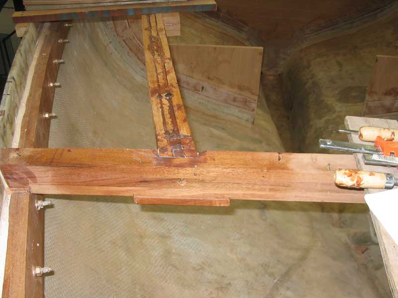
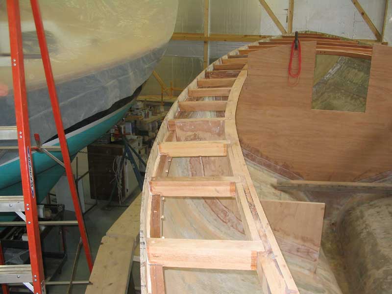
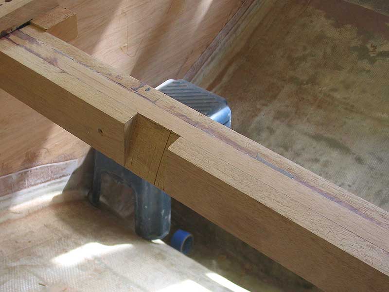
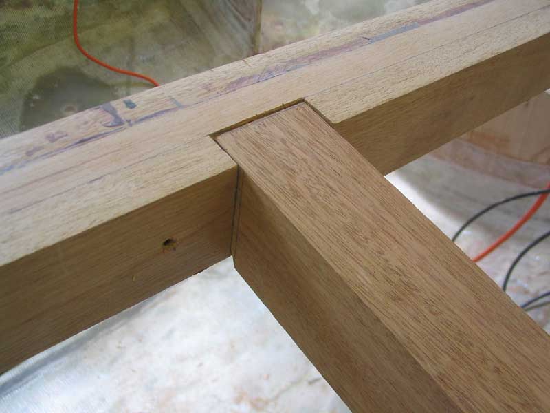
For each of 22 short deck beams, the installation process was the same. To ensure that each beam ended up square to the centerline, as well as directly across from its counterpart on the other side, I used a long straightedge across the hull to properly line everything up, and double-checked the measurements from known accurate points, such as the midships bulkhead. I did some research on appropriate means of securing the inner beam ends to the carlins. In the end, I decided upon the most commonly used method: an angled mortise with the additional support of a screw through from the inside of the carlin into the end of the deck beam. Joints like a half-lap or dovetail might at first thought seem appropriate, but in reality, given the real stresses on these joints, this sort of attachment actually weakens the deck beam significantly, in proportion to however much material on the beam is removed in order to make the joint. True mortise and tenon joints are not possible because of the physical limitations of getting the beams in place, and would be overkill anyway. |
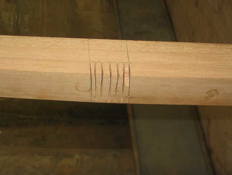 For each beam location, I marked out the
angled mortises by drawing a line 3/4" in from the outer edge of the
carlin, along the longitudinal length of the carlin, and plumbed lines
down the outer face of the carlins equal in width to the deck beam.
I used a hand saw to cut first the shoulder (outer) cuts, making the cut
so that the mortise tapered from the 3/4" depth at the top edge down
to nothing at the bottom edge. Then I made additional cuts in
between the first cuts to make it easier to chisel out the waste. For each beam location, I marked out the
angled mortises by drawing a line 3/4" in from the outer edge of the
carlin, along the longitudinal length of the carlin, and plumbed lines
down the outer face of the carlins equal in width to the deck beam.
I used a hand saw to cut first the shoulder (outer) cuts, making the cut
so that the mortise tapered from the 3/4" depth at the top edge down
to nothing at the bottom edge. Then I made additional cuts in
between the first cuts to make it easier to chisel out the waste. |
 Once I chiseled out the waste, I marked
the deck beam for the various cuts using a combination square and the same
methodology I used for marking the foredeck beams. The process is a
bit confusing to attempt to describe in writing, so once again I refer you
to the myriad texts already detailing the process. I referred mostly
to How
to Build a Wooden Boat, by David C. (Bud) McIntosh, and would
recommend this book to anyone interested in the process. With
the beams resting on top of the hull (or on top of the eventual deck
surface, if you can imagine that), I had to raise the inner edge of the
beam (on the carlin) a distance equal to the thickness of the deck
(3/4"), so I used a measuring scrap that I had around to do
this. If I had not done this, the cuts would have ended up wrong. Once I chiseled out the waste, I marked
the deck beam for the various cuts using a combination square and the same
methodology I used for marking the foredeck beams. The process is a
bit confusing to attempt to describe in writing, so once again I refer you
to the myriad texts already detailing the process. I referred mostly
to How
to Build a Wooden Boat, by David C. (Bud) McIntosh, and would
recommend this book to anyone interested in the process. With
the beams resting on top of the hull (or on top of the eventual deck
surface, if you can imagine that), I had to raise the inner edge of the
beam (on the carlin) a distance equal to the thickness of the deck
(3/4"), so I used a measuring scrap that I had around to do
this. If I had not done this, the cuts would have ended up wrong. |
 Each beam required several cuts in order to make
it fit. By using a combination square to plumb up the various points
on the carlins and sheer clamp, I ended up with a series of marks from which
I could draw out the cuts needed to, in theory, make the beam fit in the
space provided. Each beam required several cuts in order to make
it fit. By using a combination square to plumb up the various points
on the carlins and sheer clamp, I ended up with a series of marks from which
I could draw out the cuts needed to, in theory, make the beam fit in the
space provided.
|
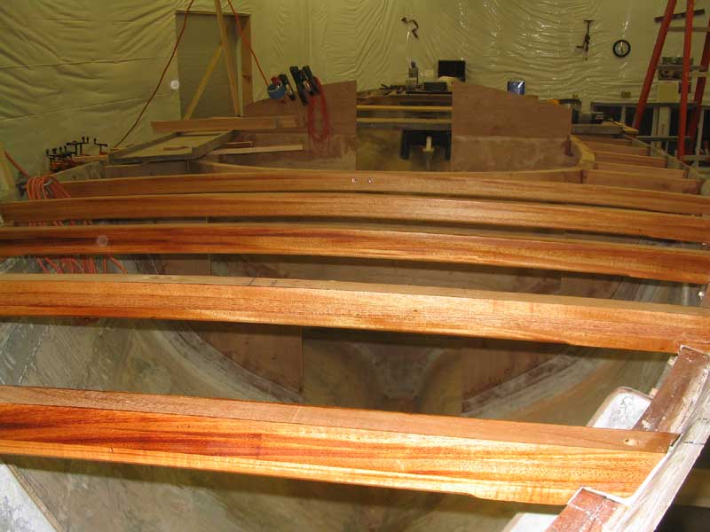
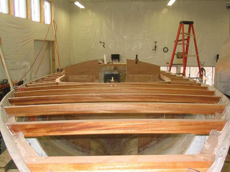
 Over the course of three days in the shop, I
cut, fit, and permanently installed all 22 short deck beams. I
installed each beam in a bed of epoxy and secured them with bronze screws,
just as I did with the full-width beams. The process became smoother
as I went, with practice, but I was happy to be done nonetheless. I
tried for good, clean fits in all cases, but the undulations of the
fiberglass inside the hull and other factors prevented perfect fits in some
areas; the epoxy made up the small differences easily. Over the course of three days in the shop, I
cut, fit, and permanently installed all 22 short deck beams. I
installed each beam in a bed of epoxy and secured them with bronze screws,
just as I did with the full-width beams. The process became smoother
as I went, with practice, but I was happy to be done nonetheless. I
tried for good, clean fits in all cases, but the undulations of the
fiberglass inside the hull and other factors prevented perfect fits in some
areas; the epoxy made up the small differences easily.
|
|
|
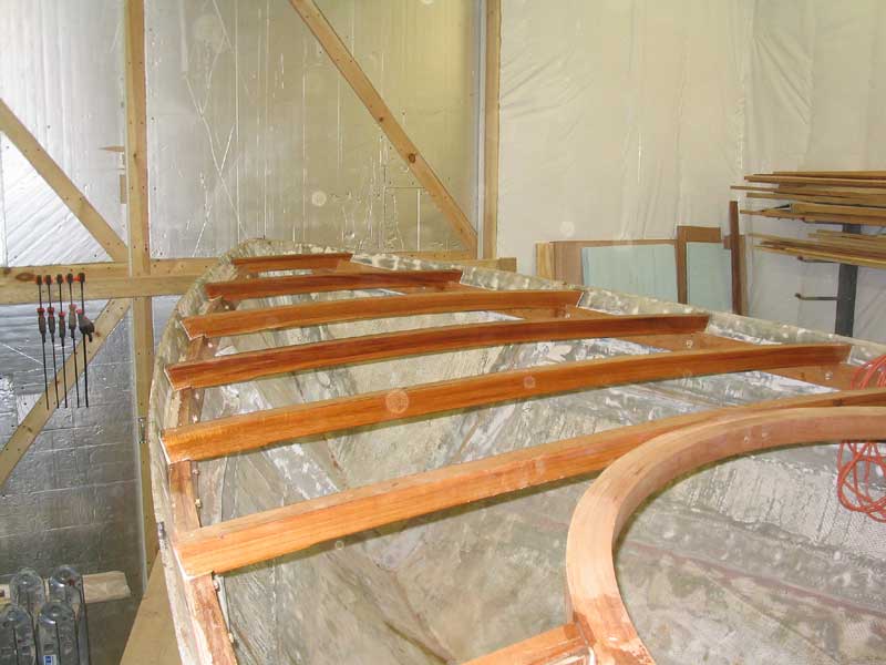
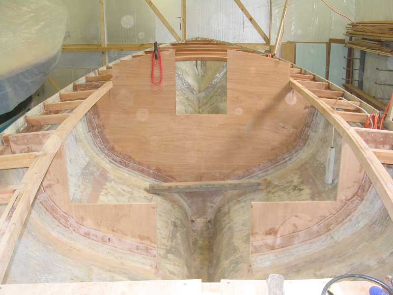
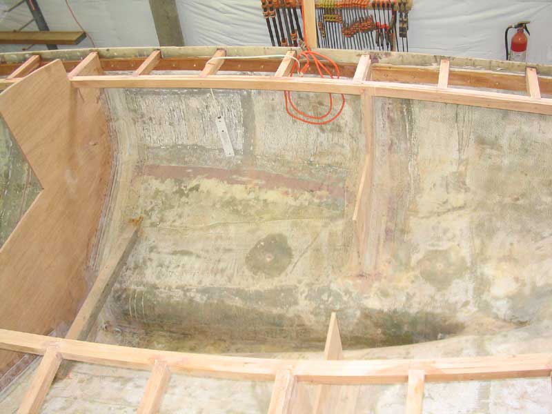 With all the deck beams in and fully secured,
the boat really took shape--and became extremely strong and stiff, as
well. I was pleased to find that the sidedecks outboard of the cockpit
(where the unsupported run is, at maximum, six feet) showed little signs of
flexing once the beams were in place and the epoxy cured. They would
get even stiffer during later steps. With all the deck beams in and fully secured,
the boat really took shape--and became extremely strong and stiff, as
well. I was pleased to find that the sidedecks outboard of the cockpit
(where the unsupported run is, at maximum, six feet) showed little signs of
flexing once the beams were in place and the epoxy cured. They would
get even stiffer during later steps.
|
|
|