|
|
~MENU~ |
| Home |
| The Concept |
| The Boat |
| Bringing Her Home |
|
Weekly Progress Log |
|
Daysailor Projects |
| The Boat Barn |
| Resources |
| Other Sites |
| Email Tim |
|
|
| From a Bare Hull: Sheer Clamp |
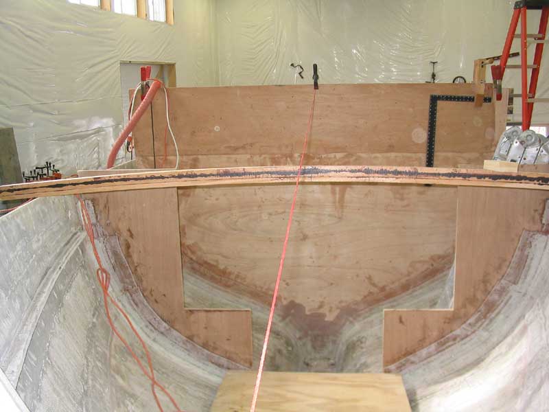
In traditional wooden boat construction (which this is not, but...), the sheer clamp is the longitudinal member that runs the length of the boat at the sheerline, and is typically a critical component for holding the whole structure together, as it ties together the hull frames and forms a basis for the deck beam installation. For my application, I've been using the term sheer clamp to describe the longitudinal member that is intended to support the deck beams above, a function that perhaps more closely describes a shelf, which is traditionally a horizontal member attached to the bottom of the sheer clamp, and upon which the beams actually rest. Debate about what the piece should truly be called aside, I needed to get serious about getting it installed so that I could continue the deck framing. Earlier, I had determined that I would build the clamp from two pieces of 3/4" mahogany, 3" wide, for a total clamp thickness of 1-1/2". I chose the thinner material to make it easier to bend the pieces against the inside of the hull, especially up forward. As a structural component, my clamp was not intended to serve the same critical functions as a clamp might in a wooden boat; it needed only to support the weight of the deck beams and deck loads above. I milled 12 boards to the proper size (3/4" x 3" x 10' long) and prepared to lay out the proper location on the hull, beginning at the bow. The clamp needed to be positioned in such a location as to allow sufficient room above for the 2-1/2" thick deck beam, plus the 3/4" deck. In concept, one might think that one could measure down from the rail the appropriate amount and locate the top of the clamp there. But the curvature and angle of the hull, particularly at the bow but also in other areas, required some additional layout and steps before the top edge of the clamp could be accurately located. When a straight-edged board, such as the clamp, is laid inside a flared/curved hull, the top edge ends up at something of an angle to the horizontal plane--that is, one corner ends up higher than the other. In the more extreme curves of the bow sections, the inner corner of the clamp edge ended up higher than the outer corner. If left uncorrected, this meant that the deck beams would only be supported by that single corner of the clamp, rather than over its entire width. Therefore, a slight upward (in this case) correction in the clamp placement was needed, the correction being equal to the gap between the end of the beam and the outer edge of the clamp. |
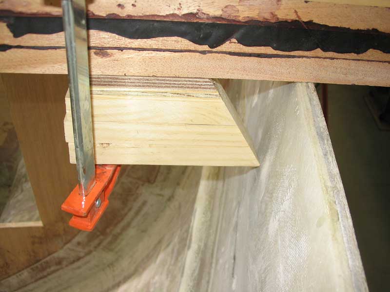
To properly determine this correction, I made a mockup of the deck beam out of three layers of scrap pine, and included the two layers of plywood that make up the deck thickness--since my deck is intended to end up flush with the edge of the hull. I cut one end of the beam mockup at an angle, with the point at the bottom end, which prevented any unnecessary parts of the mockup from getting in the way of the layout process.
|
 Using
the same techniques as I used to locate the bulkheads,
I marked the hull on each side of each of the six frame locations (bow
sections only). To locate the clamp top at each frame location, I
laid the beam mold across the hull, lining up the centerline with a mark
on the beam, and laying the edges of the beam at the appropriate marks on
the hull. Then, I clamped my deck beam mockup to the bottom of the
beam mold so that the corner of the angled cut contacted the
hull. Using
the same techniques as I used to locate the bulkheads,
I marked the hull on each side of each of the six frame locations (bow
sections only). To locate the clamp top at each frame location, I
laid the beam mold across the hull, lining up the centerline with a mark
on the beam, and laying the edges of the beam at the appropriate marks on
the hull. Then, I clamped my deck beam mockup to the bottom of the
beam mold so that the corner of the angled cut contacted the
hull. |
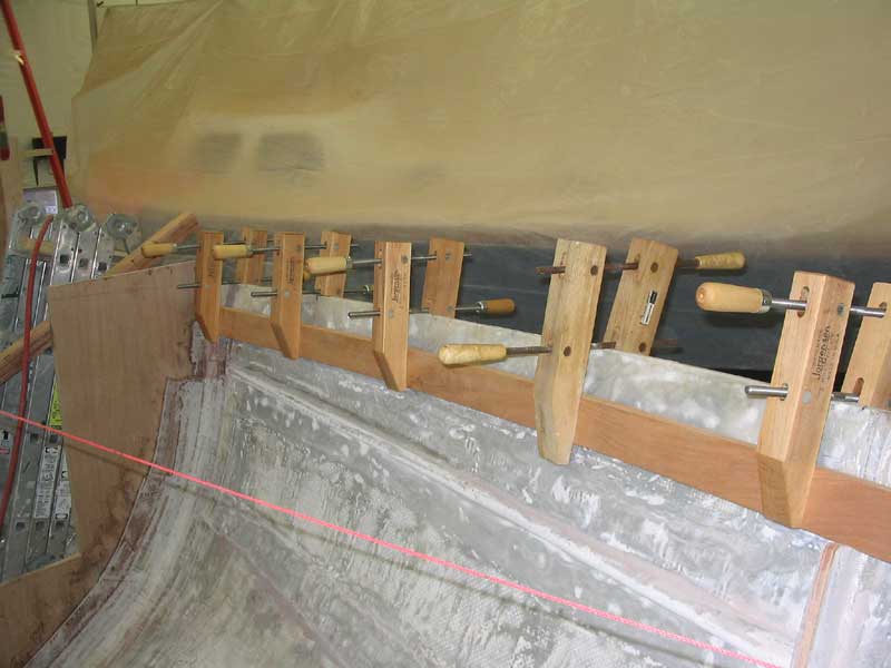
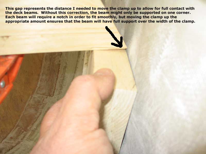 Next,
I placed a mockup of the 1-1/2" x 3" clamp against the hull,
with the inner edge resting flush against the bottom of my beam
mockup. In an ideal situation, the clamp block would rest smoothly
against the bottom of the beam, offering its full support. But the
curvature and flare of the hull meant that, as is common, the beam,
represented by the mockup here, contacted only the inner corner of the
clamp. In order to ensure full support, the clamp had to move up a
distance equal to the gap at the outer edge. Click the photo for
more detail. Next,
I placed a mockup of the 1-1/2" x 3" clamp against the hull,
with the inner edge resting flush against the bottom of my beam
mockup. In an ideal situation, the clamp block would rest smoothly
against the bottom of the beam, offering its full support. But the
curvature and flare of the hull meant that, as is common, the beam,
represented by the mockup here, contacted only the inner corner of the
clamp. In order to ensure full support, the clamp had to move up a
distance equal to the gap at the outer edge. Click the photo for
more detail. |
|
|