|
|
~MENU~ |
| Home |
| The Concept |
| The Boat |
| Bringing Her Home |
|
Weekly Progress Log |
|
Daysailor Projects |
| The Boat Barn |
| Resources |
| Other Sites |
| Email Tim |
|
|
| From a Bare Hull: Bulkheads |
|
Hull Leveling | Basic Layout | Chainplate Bulkhead | Mid Bulkhead | After Bulkhead | Fillets & Tabbing | Limbers |
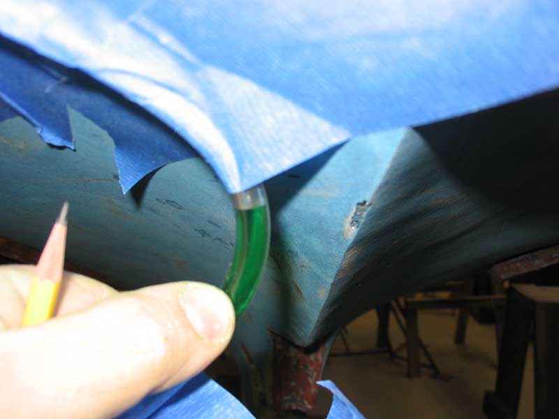
Leveling the Hull Before diving into bulkhead installation, I wanted to make sure the hull was level. There are probably any number of ways to do this; certainly one of the various laser-type level tools would have worked, but I didn't have one. Plus, I enjoy (in a masochistic sense) finding ways to deal with these issues using the materials on hand. I had used a water level a dozen years earlier, and figured it would be an easy and surefire way to get the results I needed.
|
Next, I had the idea to force water into the hose using a spray bottle or something. I found a good spray bottle in the garage and filled it with the water, and had some success. But the bottle forced a lot of air into the hose too, and it was slow going. Plus, there were those big air pockets halfway down the hose that simply wouldn't move. My next plan involved a combination of the
spray bottle, and climbing my big stepladder to get gravity working on my
side. This helped to an extent, but it was annoying when I
accidentally dropped one of the hose ends...I'm sure the sight of me
hustling down the big ladder as quickly as possible to save the hose and
the precious amounts of water within would have been funny, had anyone
been there to see it. After a time, I got the hose filled to within
a foot |
 With
the dumbness over, I prepared to actually level the boat. From
previous experience, I knew that the original scribed waterline was
actually straight, so I knew that I could use this as a valid reference
point. Beginning with the fore and aft level, I attached the hose at
the waterline at the stern, and ran the other end to the forward end of
the waterline, where I secured it in place willy-nilly, without regard to
the water level inside. With some minor adjustment of the hose, I
got the water level inside to match exactly the stern waterline, and then
went to the bow to see how far off the boat was. Since the water
level inside the hose was located exactly at the stern waterline, I knew
that however different the level was at the bow would equate to how much
out of level the hull was. I was astonished (and pleased) to see
that the water level indicated that the bow was exactly level (or as close
as could be practicable) with the stern, with no adjustment needed.
Who would have guessed it. With
the dumbness over, I prepared to actually level the boat. From
previous experience, I knew that the original scribed waterline was
actually straight, so I knew that I could use this as a valid reference
point. Beginning with the fore and aft level, I attached the hose at
the waterline at the stern, and ran the other end to the forward end of
the waterline, where I secured it in place willy-nilly, without regard to
the water level inside. With some minor adjustment of the hose, I
got the water level inside to match exactly the stern waterline, and then
went to the bow to see how far off the boat was. Since the water
level inside the hose was located exactly at the stern waterline, I knew
that however different the level was at the bow would equate to how much
out of level the hull was. I was astonished (and pleased) to see
that the water level indicated that the bow was exactly level (or as close
as could be practicable) with the stern, with no adjustment needed.
Who would have guessed it. |
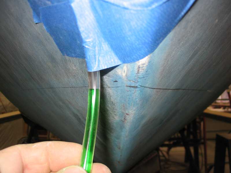
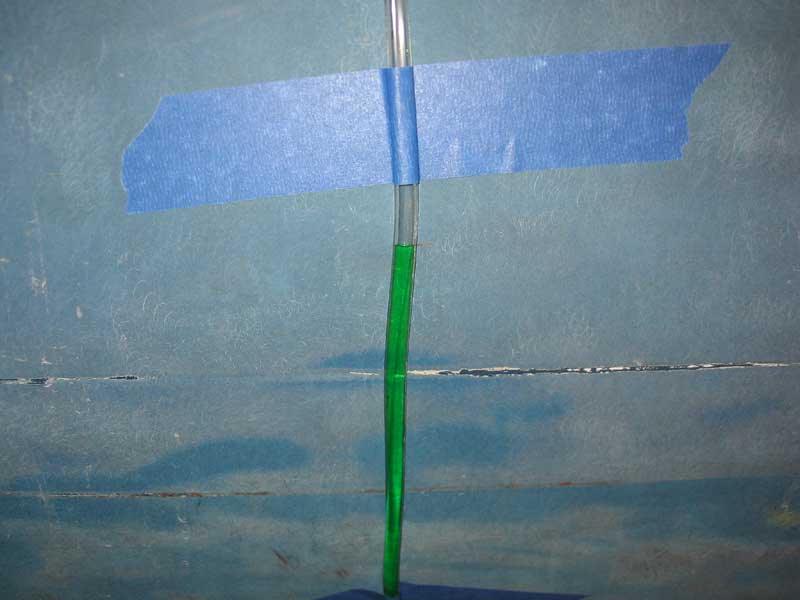 Next,
I moved the level to the sides of the hull, again choosing the scribed
waterline as a reference datum. I taped the water level in place on
each side, opened the valves, and noted the location of the water inside
on each side of the hull, measuring up from the scribed waterline.
Again, I discovered that the hull was in fact level from side to side
already. This was great because it saved me plenty of work and
adjusting the jackstands, etc. With the hull leveled in both
directions, I was ready to continue with the layout for the bulkheads
installation. Next,
I moved the level to the sides of the hull, again choosing the scribed
waterline as a reference datum. I taped the water level in place on
each side, opened the valves, and noted the location of the water inside
on each side of the hull, measuring up from the scribed waterline.
Again, I discovered that the hull was in fact level from side to side
already. This was great because it saved me plenty of work and
adjusting the jackstands, etc. With the hull leveled in both
directions, I was ready to continue with the layout for the bulkheads
installation. |
Basic Layout and Measurement: Chainplate Bulkhead 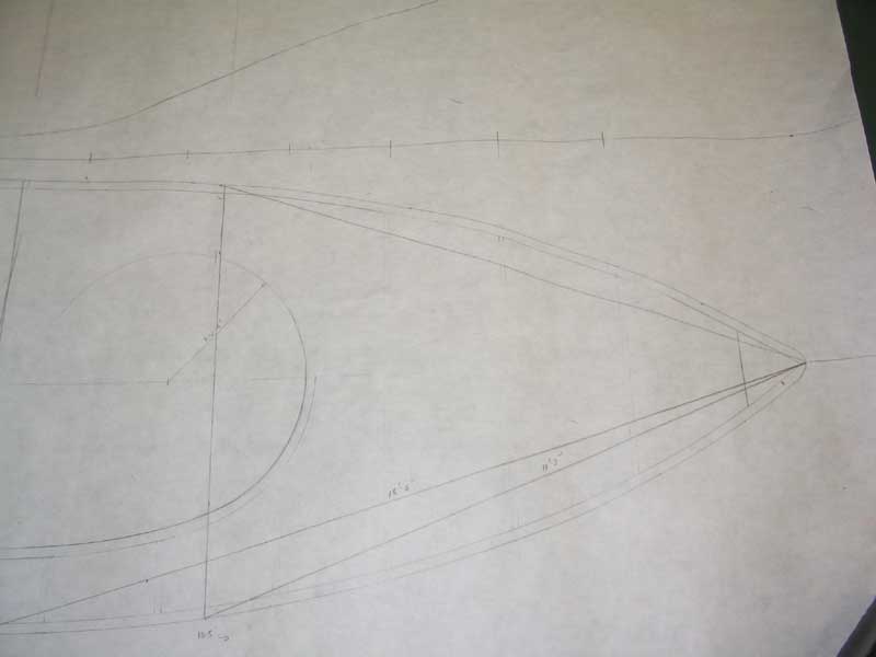 Since
I now knew that the hull was level, I could begin the next step:
locating the bulkheads. With no datum inside the boat, I had to
start from scratch. My first step was to consult with my rough deck
framing sketch, along with some drawings of the original Triton and the
supposed locations of things like the mast step. I noted these
locations on my scale drawing, and measured the distance aft from the
stem, both in a straight line along the centerline, and also at an angle
from the stem back to the hull edge. The angle measurement was
actually more important, since replicating that particular measurement on
the boat would be much easier than trying to get a mark off a
centerline. I determined the first bulkhead (where the chainplates
would eventually be installed) was 10.5' aft on the centerline, and
11'-3" along the angle to the side of the hull. I carefully set
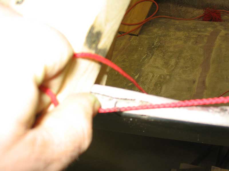
up a string secured to the stem on centerline, and then measured along it
to the proper distance, where I made a mark. Then I could easily use
the marked string to locate the bulkhead on each side of the hull, the
proper distance from the bow. This ensured that the bulkhead would
end up square to the centerline of the hull. Since
I now knew that the hull was level, I could begin the next step:
locating the bulkheads. With no datum inside the boat, I had to
start from scratch. My first step was to consult with my rough deck
framing sketch, along with some drawings of the original Triton and the
supposed locations of things like the mast step. I noted these
locations on my scale drawing, and measured the distance aft from the
stem, both in a straight line along the centerline, and also at an angle
from the stem back to the hull edge. The angle measurement was
actually more important, since replicating that particular measurement on
the boat would be much easier than trying to get a mark off a
centerline. I determined the first bulkhead (where the chainplates
would eventually be installed) was 10.5' aft on the centerline, and
11'-3" along the angle to the side of the hull. I carefully set
up a string secured to the stem on centerline, and then measured along it
to the proper distance, where I made a mark. Then I could easily use
the marked string to locate the bulkhead on each side of the hull, the
proper distance from the bow. This ensured that the bulkhead would
end up square to the centerline of the hull. |
|
|
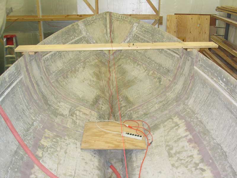
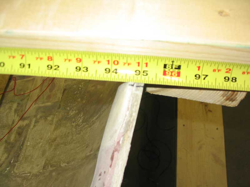 To
create a solid, temporary brace across the hull, which would be invaluable
in laying out the actual bulkhead shape, and to also ensure that the hull
didn't move significantely while the bulkhead was being measured and
installed, I laid a length of 2x10 across the hull. From the
drawing, I measured that the beam of the boat in that area should be about
7'-11". When I measured the boat, I found that it
was...7'-11", or close enough. To secure the beam and prevent
the hull from changing shape, I screwed scraps of 2x4 to the bottom of the
beam on each side of the hull, inside and outside. Later, I added
some clamps to prevent the board from sliding at all. To
create a solid, temporary brace across the hull, which would be invaluable
in laying out the actual bulkhead shape, and to also ensure that the hull
didn't move significantely while the bulkhead was being measured and
installed, I laid a length of 2x10 across the hull. From the
drawing, I measured that the beam of the boat in that area should be about
7'-11". When I measured the boat, I found that it
was...7'-11", or close enough. To secure the beam and prevent
the hull from changing shape, I screwed scraps of 2x4 to the bottom of the
beam on each side of the hull, inside and outside. Later, I added
some clamps to prevent the board from sliding at all. |
|
|
|
|