|
|
~MENU~ |
| Home |
| The Concept |
| The Boat |
| Bringing Her Home |
|
Weekly Progress Log |
|
Daysailor Projects |
| The Boat Barn |
| Resources |
| Other Sites |
| Email Tim |
|
|
|
From a Bare Hull: Interior Basics (Page 3) |
|
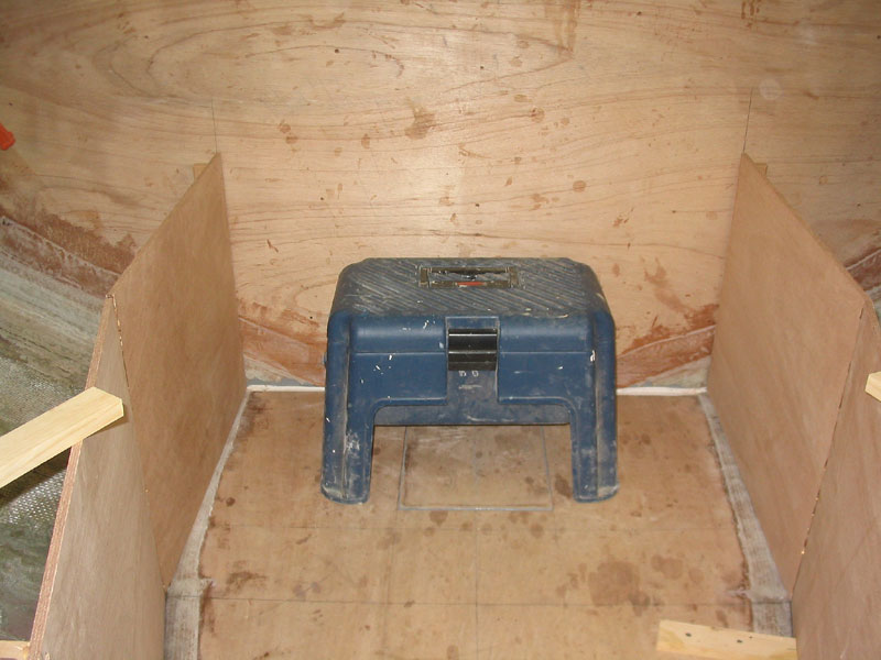
V Berth and Settee Structure My vision for the interior was pretty basic, but it took some thought before I could begin laying things out, once the cabin sole substrate was installed. I planned a standard vee-berth, with open "V" area and filler cushion, in the space forward of the forwardmost bulkhead. Then, aft of that, I planned a pair of short seats, or settees, and some basic countertops/lockers elsewhere. Aspects of the overall plan will become more clear as we proceed. The first item of importance was allowing enough room in the "V" of the vee berth area for a portable toilet. I planned on locating the toilet on the cabin sole forward of the mast, as far forward as practicable given the limitations of the space. From a catalog, I obtained the basic dimensions of an appropriate unit, which I used to begin the layout of the vertical pieces of plywood that define the space. To be safe, however, I actually ordered the toilet now, so that I could ensure that the model I had chosen would fit, and that no product changes might occur in the meantime that could affect its overall dimensions. (Question: why do junky plastic porta-potties cost so much? There's, like, $5 worth of plastic in it, if that.) |
|
|
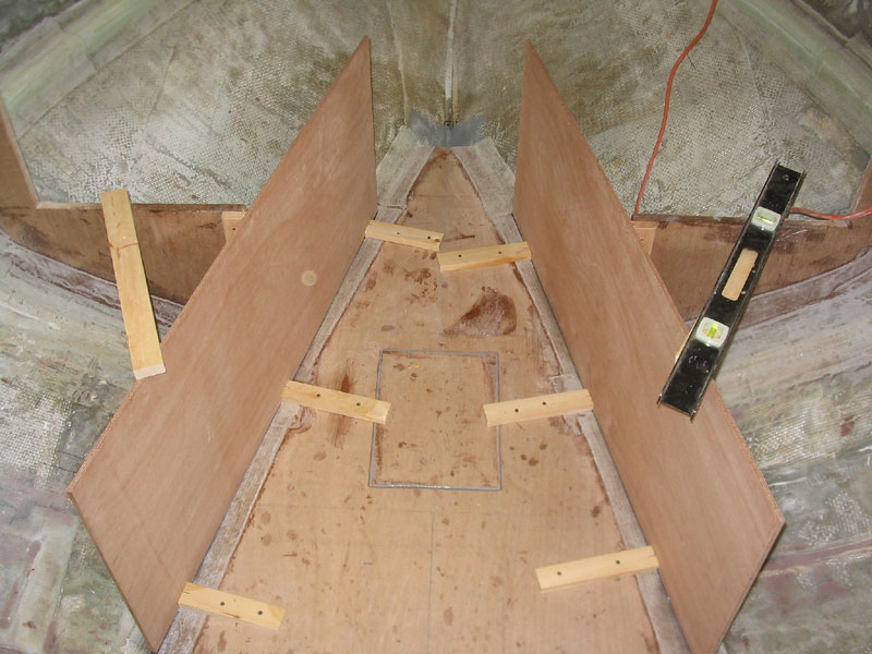
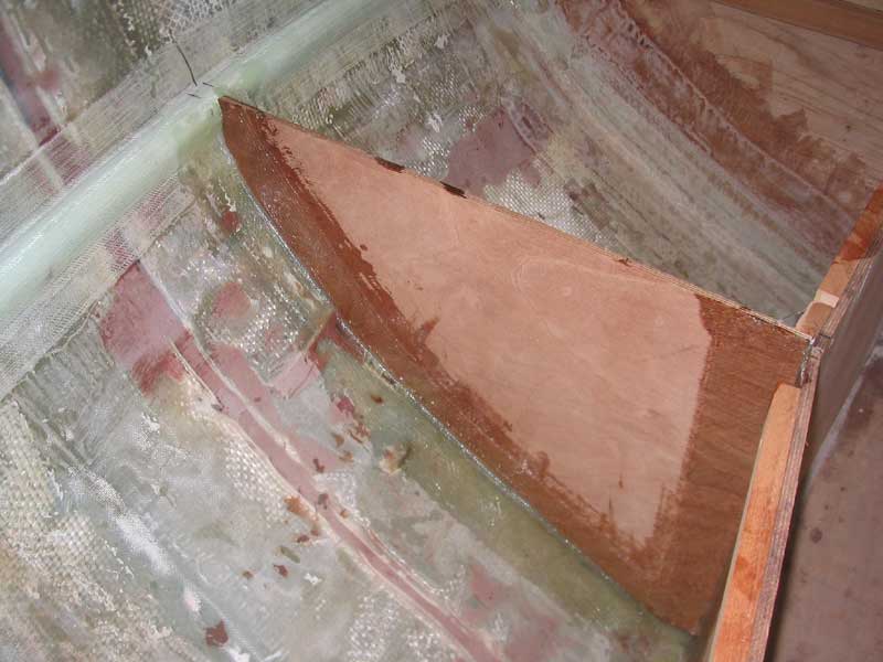
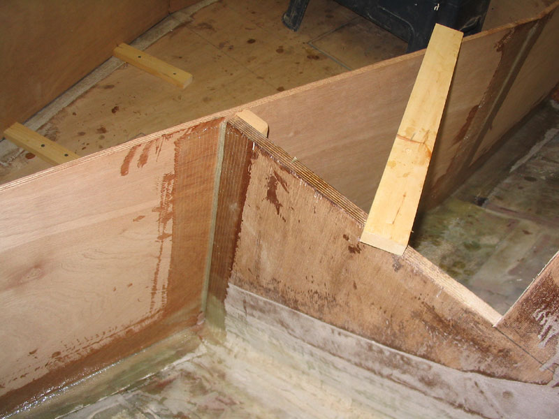
 With
the angled pieces set in place, I continued by cutting and fitting two final
pieces of plywood that ran from the aft end of the forward sections all the
way to the mid bulkhead, and bout 24" aft. I installed these
after pieces parallel to the centerline, which was more or less what the
curvature of the hull in that area would allow. After some minor
trimming to get the pieces to fit properly, I secured them temporarily with
hot glue and braces. I double checked all the pieces for level and
plumb. I installed some mahogany cleats at the forward bulkhead and
mid bulkhead to help support the new material; like all my mahogany cleats,
I chamfered one edge and sanded the pieces smooth. With
the angled pieces set in place, I continued by cutting and fitting two final
pieces of plywood that ran from the aft end of the forward sections all the
way to the mid bulkhead, and bout 24" aft. I installed these
after pieces parallel to the centerline, which was more or less what the
curvature of the hull in that area would allow. After some minor
trimming to get the pieces to fit properly, I secured them temporarily with
hot glue and braces. I double checked all the pieces for level and
plumb. I installed some mahogany cleats at the forward bulkhead and
mid bulkhead to help support the new material; like all my mahogany cleats,
I chamfered one edge and sanded the pieces smooth.
|
|
|
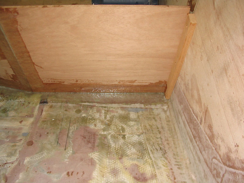
 I
tabbed the new partitions in place on one side (the side that would be
hidden inside lockers) with a single layer of 15 oz. biaxial tape and epoxy
resin. I tabbed their entire lengths along the bottom edge, the seam
between the two sections of plywood, and the intersections between the
vertical partitions and the two bulkheads. Additional structure
to be added later would further reinforce the pieces, but the tabbing,
combined with the vertical support afforded by the cleats at the bulkheads,
was plenty to ensure a secure fit. I
tabbed the new partitions in place on one side (the side that would be
hidden inside lockers) with a single layer of 15 oz. biaxial tape and epoxy
resin. I tabbed their entire lengths along the bottom edge, the seam
between the two sections of plywood, and the intersections between the
vertical partitions and the two bulkheads. Additional structure
to be added later would further reinforce the pieces, but the tabbing,
combined with the vertical support afforded by the cleats at the bulkheads,
was plenty to ensure a secure fit.
|
 Some
time later, I sanded all the new tabbing to remove any sharp edges and
slightly smooth the surface for future painting. Some
time later, I sanded all the new tabbing to remove any sharp edges and
slightly smooth the surface for future painting.
|
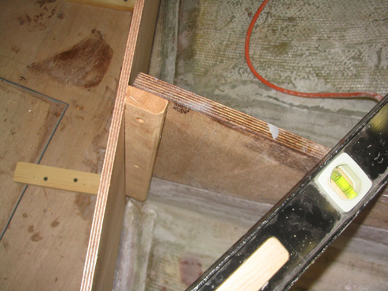
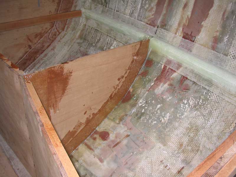
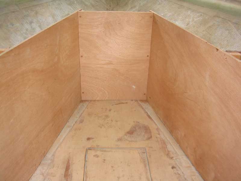 I
continued work on the interior substructure by milling and installing a
simple piece of plywood at the forward end of the cabin, in the
"V" of the forward berth. After marking out a pre-determined
distance forward of the mid bulkhead (which location was initially
determined by the size of the chosen Porta-Potti and the angle of the side
structures), I plumbed lines up on each side and then installed mahogany
cleats milled to fit. Finally, I cut a small piece of plywood, with
the sides beveled to match the angles as necessary, and screwed it in place. I
continued work on the interior substructure by milling and installing a
simple piece of plywood at the forward end of the cabin, in the
"V" of the forward berth. After marking out a pre-determined
distance forward of the mid bulkhead (which location was initially
determined by the size of the chosen Porta-Potti and the angle of the side
structures), I plumbed lines up on each side and then installed mahogany
cleats milled to fit. Finally, I cut a small piece of plywood, with
the sides beveled to match the angles as necessary, and screwed it in place.
|
|
|
|
|
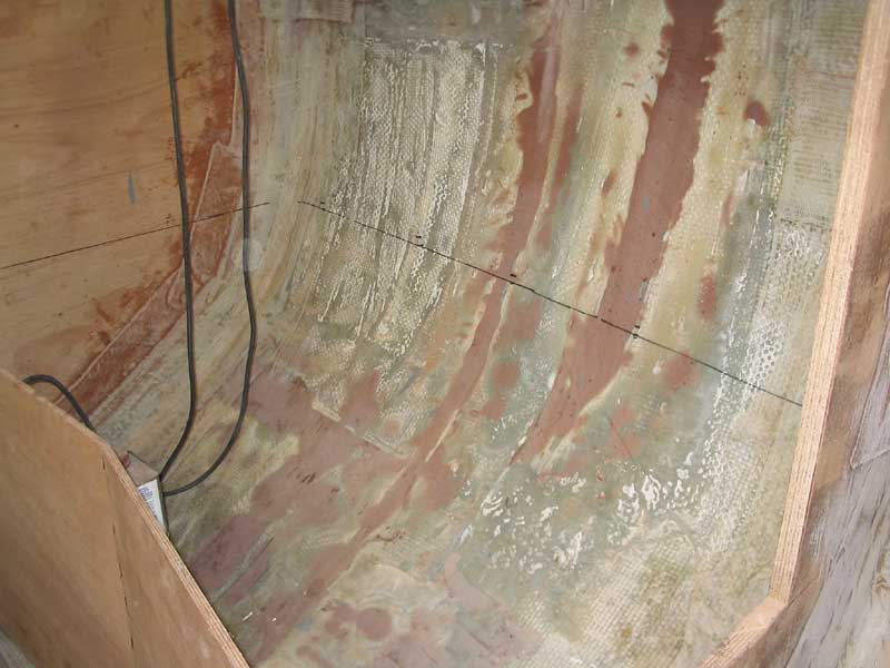
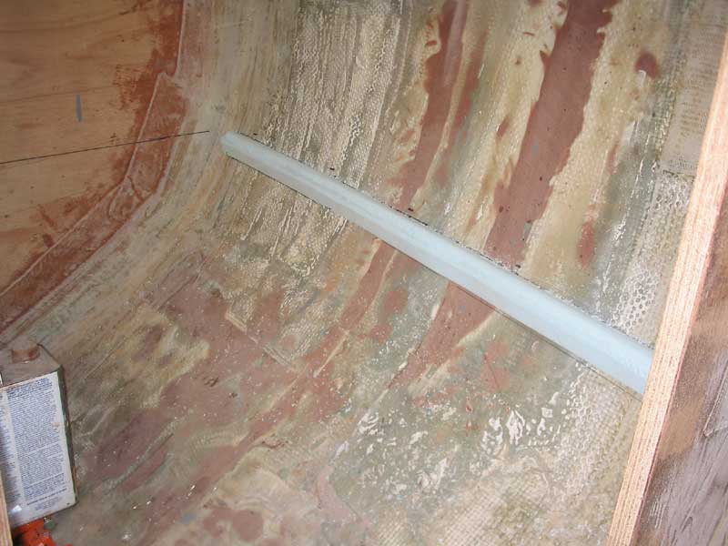 I decided the best course of action for now was
to install a cleat along the hull at the same height as the tops of the
plywood settee structure I had previously installed, so that I could then
place plywood across the entire area, against which any additional
cabinetry, lockers, and backrests could be constructed later on. To
build the cleat, I first transferred a level line from the settee structure
out to the hull in several locations on each side, using a level to strike
the line across. Then, much as I did when installing a similar cleat
for the V-berth platform earlier, I cut some
foam to shape, beveling the top side as needed to make it level, and the
bottom side at 45° to allow for successful glassing; then, I hot-glued it to the hull temporarily before securing it in
place with some 6" biaxial tape over the top. I decided the best course of action for now was
to install a cleat along the hull at the same height as the tops of the
plywood settee structure I had previously installed, so that I could then
place plywood across the entire area, against which any additional
cabinetry, lockers, and backrests could be constructed later on. To
build the cleat, I first transferred a level line from the settee structure
out to the hull in several locations on each side, using a level to strike
the line across. Then, much as I did when installing a similar cleat
for the V-berth platform earlier, I cut some
foam to shape, beveling the top side as needed to make it level, and the
bottom side at 45° to allow for successful glassing; then, I hot-glued it to the hull temporarily before securing it in
place with some 6" biaxial tape over the top.
|
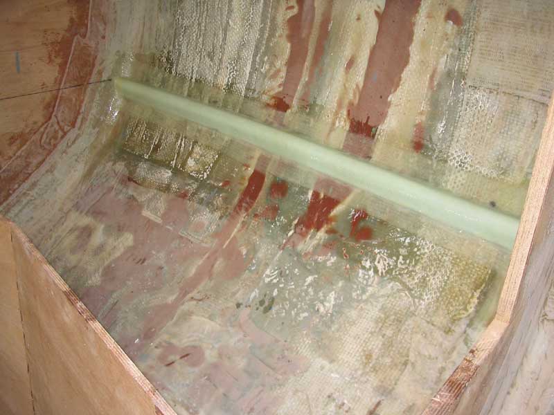 The
next day, the new fiberglass was cured, and I sanded it briefly to
remove rough edges and prepare if for further steps. The
next day, the new fiberglass was cured, and I sanded it briefly to
remove rough edges and prepare if for further steps.
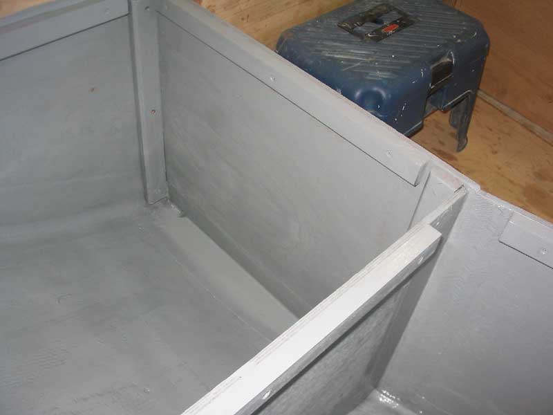
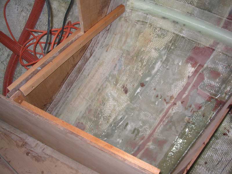
The next order of business was to install a plywood divider in the 48" space between the chainplate bulkhead and the midships bulkhead. This small bulkhead would provide needed support for the settee platform, which could not span the distance without flexing (unless much thicker material was used, which I did not want to do). |
|
Fabricating the bulkheads was simple enough. After deciding exactly where they woudl lie longitudinally (23-1/2" aft of the chainplate bulkhead, or just aft of the point where the vertical base angles and changes direction as it runs aft), I laid a scrap pine board across between the settee base (what in the world do you call the vertical, longitudinal pieces that form the inside edge of the settees, anyway? I guess they're bulkheads too, but somehow that doesn't seem descriptive enough.) and the new cleat against the hull. With this board properly positioned, I measured straight down to the hull at pre-marked 3" intervals along the board, taking note of the measurement in each case. From this, it was easy to lay out the shape of the bulkhead on some 3/8" Meranti plywood. Think of it as a tick strip on the horizontal, if you will.
|
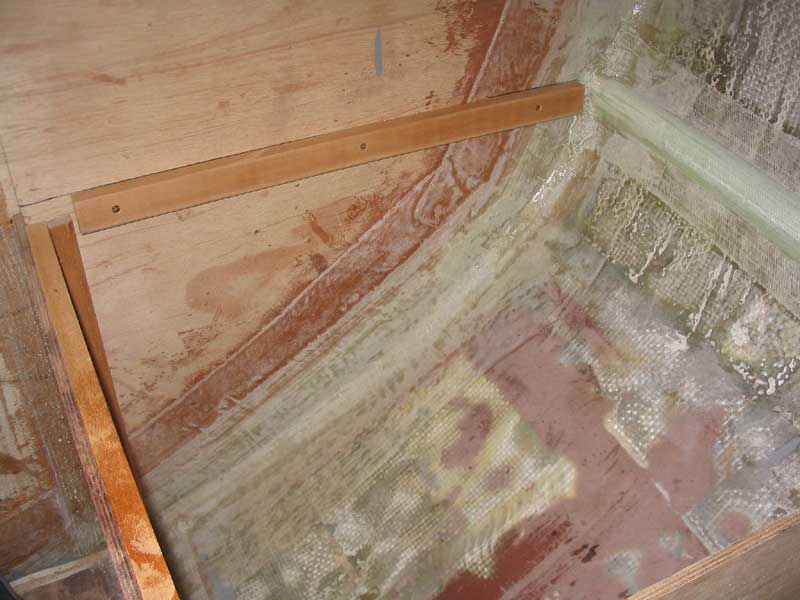
 To
secure the bulkheads, I first installed a mahogany cleat on the inside face
of each of the longitudinal bulkheads, ensuring that it was plumb.
Then, I screwed the new bulkhead to the cleats, and secured the hull side in
place temporarily with hot-melt glue. Finally, I tabbed the bulkheads
in place with 15 oz. biaxial tape on each side, and on the vertical seam
opposite the mahogany cleats. To
secure the bulkheads, I first installed a mahogany cleat on the inside face
of each of the longitudinal bulkheads, ensuring that it was plumb.
Then, I screwed the new bulkhead to the cleats, and secured the hull side in
place temporarily with hot-melt glue. Finally, I tabbed the bulkheads
in place with 15 oz. biaxial tape on each side, and on the vertical seam
opposite the mahogany cleats.
|
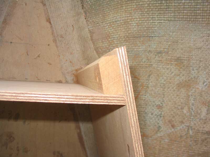
 The
plywood settee and V-berth tops would require additional support in many
areas where they intersected with the various bulkheads. To this end,
I milled a number of pieces from solid mahogany, which I installed as cleats
along the bulkheads on each side, as well as on the inside of the
longitudinal bulkheads that define the settees. I chamfered the lower
edge of each cleat with a router, then sanded the pieces relatively smooth
to remove any rough or sharp edges; this is one of those details that really
makes a difference, both in looks and in function. The
plywood settee and V-berth tops would require additional support in many
areas where they intersected with the various bulkheads. To this end,
I milled a number of pieces from solid mahogany, which I installed as cleats
along the bulkheads on each side, as well as on the inside of the
longitudinal bulkheads that define the settees. I chamfered the lower
edge of each cleat with a router, then sanded the pieces relatively smooth
to remove any rough or sharp edges; this is one of those details that really
makes a difference, both in looks and in function.
|
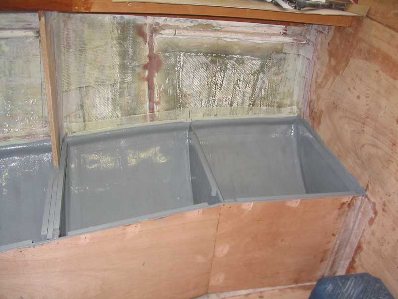
 With
the basic structure of the cabin berths and settees complete, I painted out
the areas beneath the level of the eventual platforms with two coats of
Interlux Bilgekote gray, finishing off the areas. With
the basic structure of the cabin berths and settees complete, I painted out
the areas beneath the level of the eventual platforms with two coats of
Interlux Bilgekote gray, finishing off the areas.
|
|
|
|
|