
| Hattie
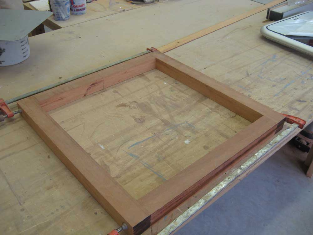
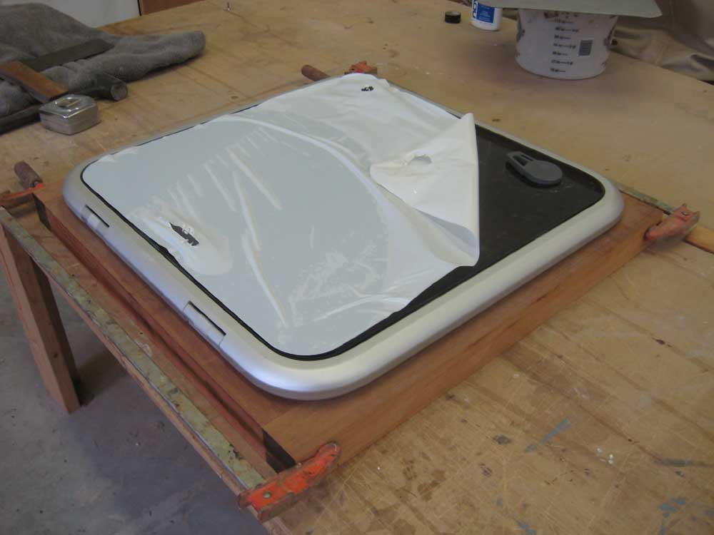
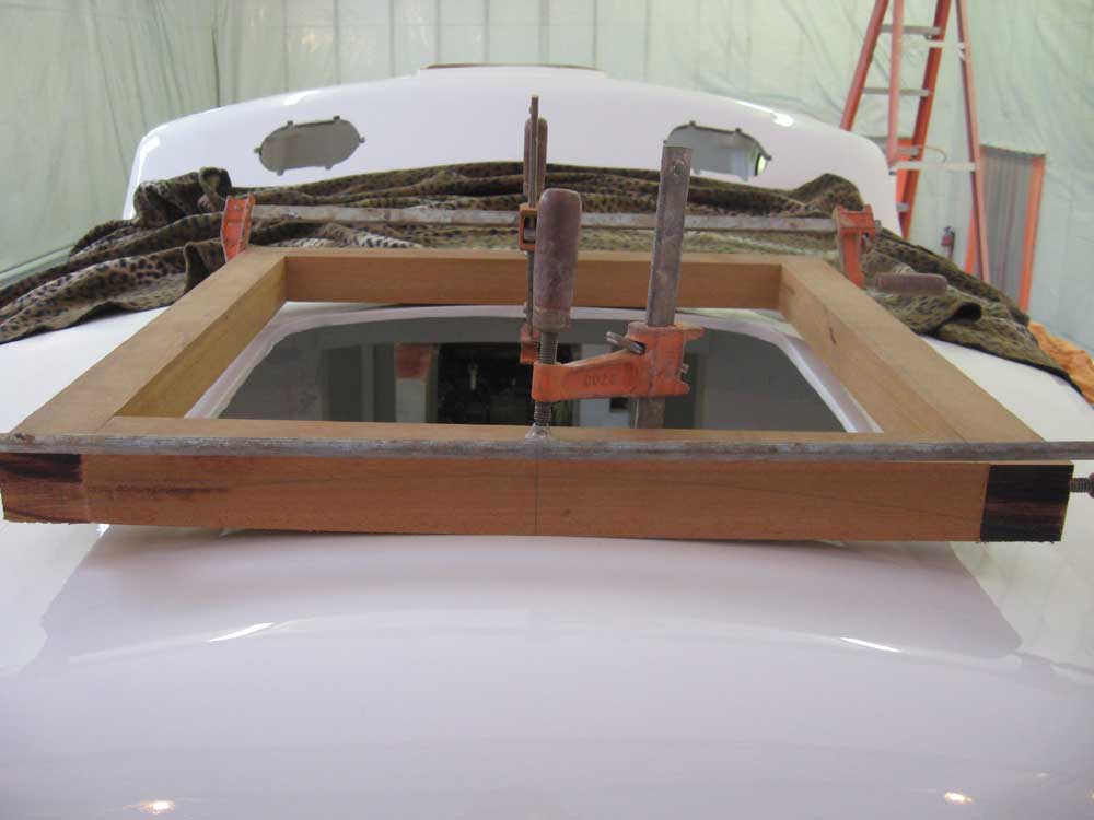
Mae | Monday, June 22, 2009 It was time to shift gears, now that the painting was complete. Although the paint project had been the main focus for the boat's stay in the shop, there were a number of other tasks ahead to complete, within the confines of the chosen scope of the overall job. Chief among the immediate concerns was preparing the boat for outdoor storage once more: this meant a focus on closing up the various openings, namely the hatches and ports. To that end, I began the day working on the forward hatch installation. To make the flat hatch fit the crowned coachroof, I needed to build a wooden framework to conform to the shape of the deck, and for the hatch to rest upon. With the hatch set loosely in place in the opening, I confirmed the overall fit, and made a quick measurement of the minimum height of the new wooden surround, and confirmed my previously-planned hatch surround width of one inch exposure beyond the edge of the hatch mounting flange. This corresponded properly with the deck layout I'd done during the painting stage, leaving a 1-1/2" reveal around the outer edge of the hatch frame to the nonskid, consistent with the other areas on deck. Back at the bench, I determined that the overall width of the hatch frame pieces would be 2" (1" flange and 1" reveal), so I milled some 8/4 mahogany to the proper width, and then cut four pieces as needed to build the frame. (I know, my chop saw blade is pathetically dull.) Once I had the basic framework cut, I clamped the pieces temporarily together and brought them to the boat so I could scribe the frame to fit the deck. |
 |
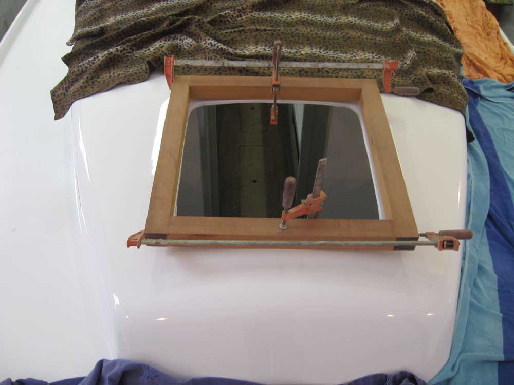
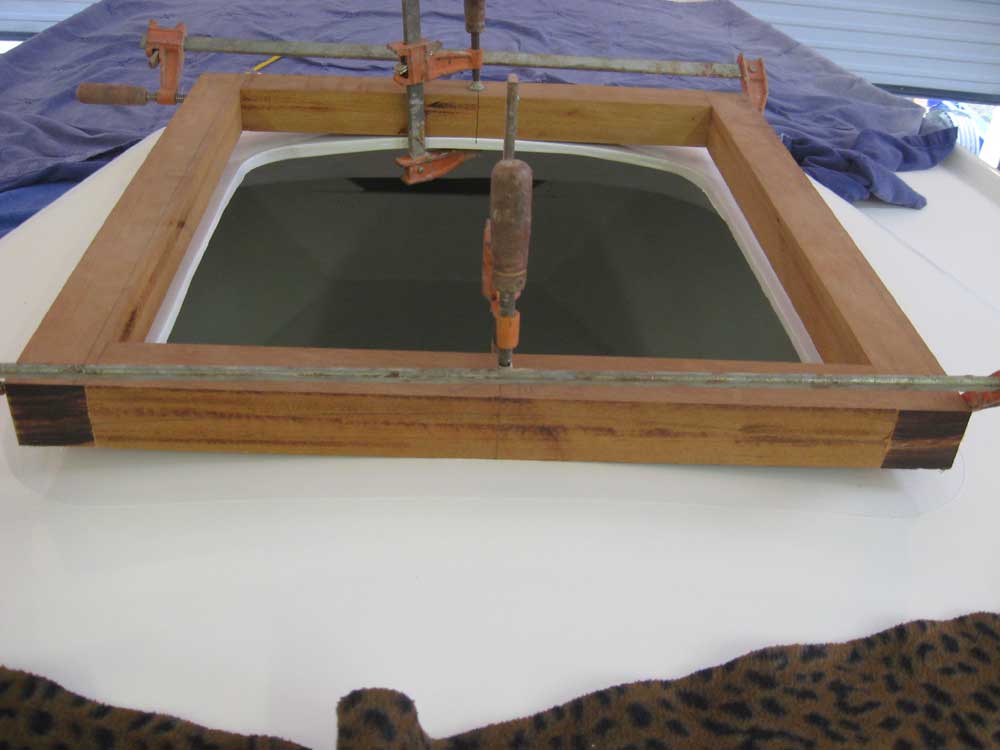
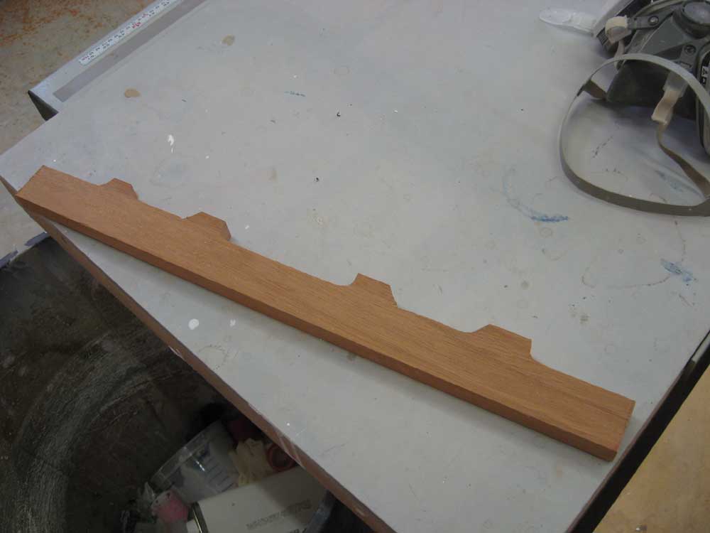
| With the frame clamped and centered in the opening, I used a compass to scribe the curvature on the fore and after ends of the frame. Back on the bench, I made the requisite cuts with a jigsaw, and then used a power plane to bevel the bottom edges of the two longitudinal frame members appropriately, as dictated by the arc on the fore and aft pieces. |
 |
|
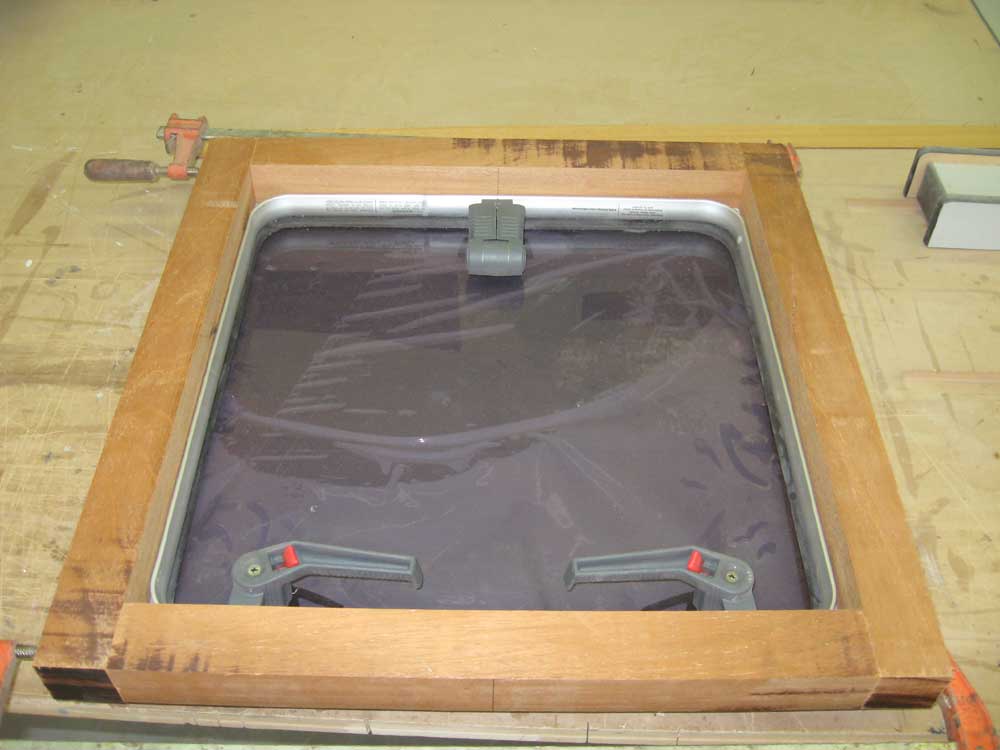
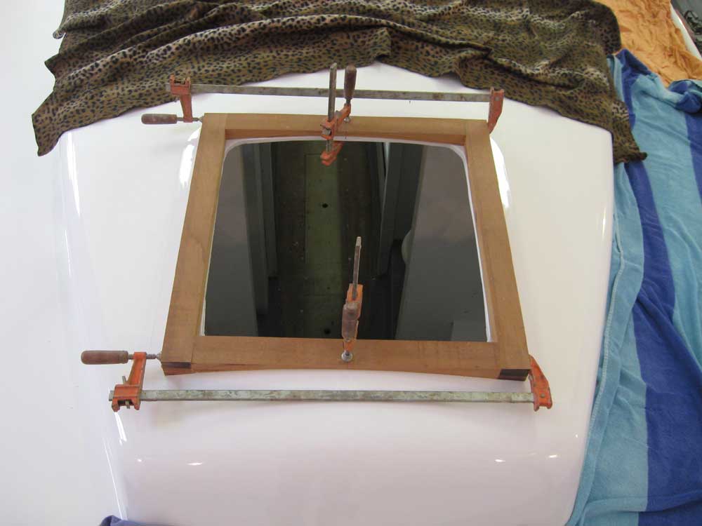
With the frame thusly shaped in the rough and clamped together again, I test-fit it on board once more. The fit was close enough for now, but I'd fine tune it once the frame was glued together. |

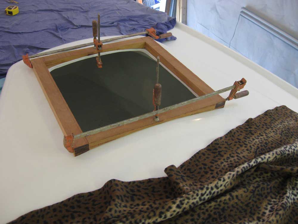 |
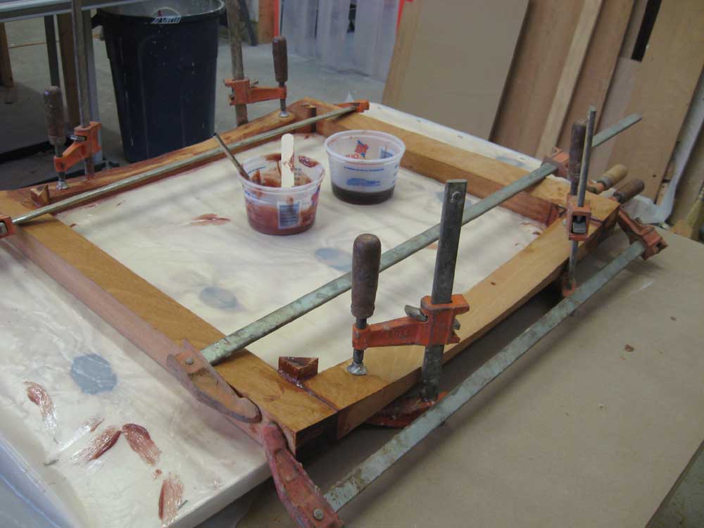
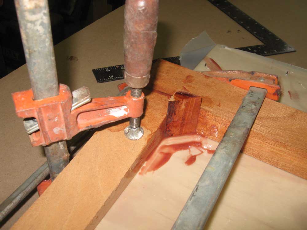
| Cutting the curves on the wood had released some pent-up inner grain tension, and as a result the curved end pieces wanted to bend just a little rather than lay flat. Since I wanted the hatch frame to glue up flat and true, I lightly clamped the end frames to a plastic-covered sheet of plywood to hold them flat, and then epoxy-glued the edge frames in place. To strengthen the corners, as well as--and more importantly--to fill in what would be a large void beneath the metal hatch flange (which was curved at the corners), I added some triangular pieces of mahogany cut at a 45° angle, and about 1" on a side, securing them with additional epoxy at each corner. I left the pieces long for later trimming. |
 |
|
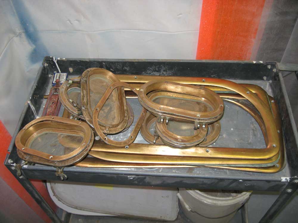
Among the other key items the owner wanted me to address was the ports' installation. To that end, I unpacked the port frames and ports from their storage, and determined what materials I'd need for their installation, from sealant to fasteners, and set the ports aside for now pending additional preparations. |
 |
|
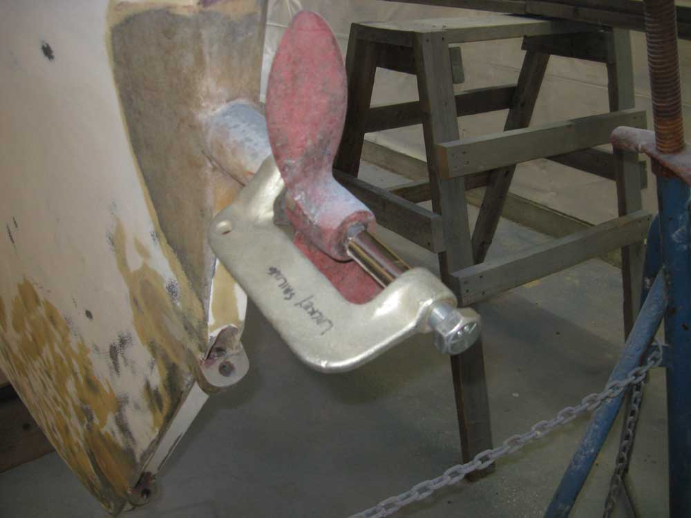
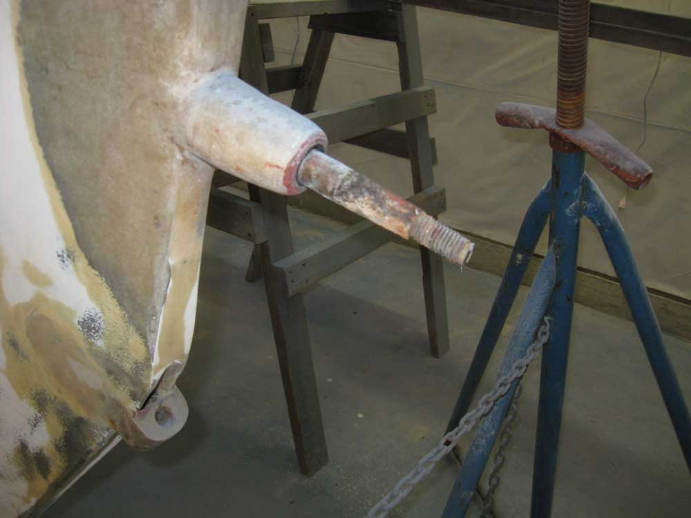
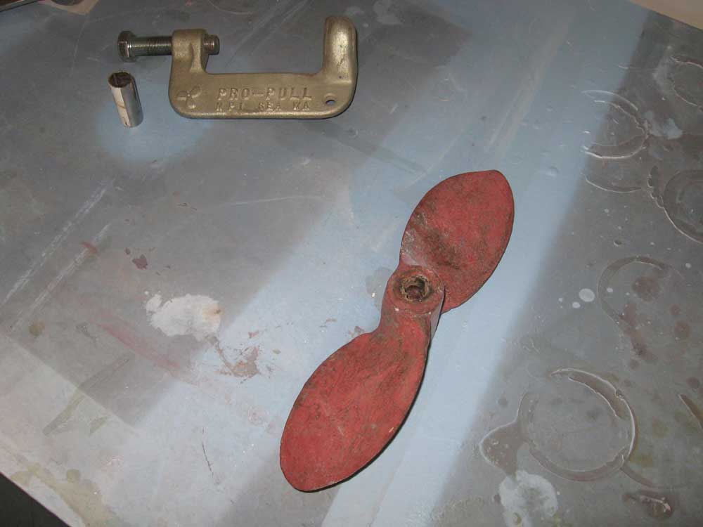
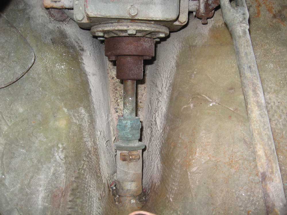
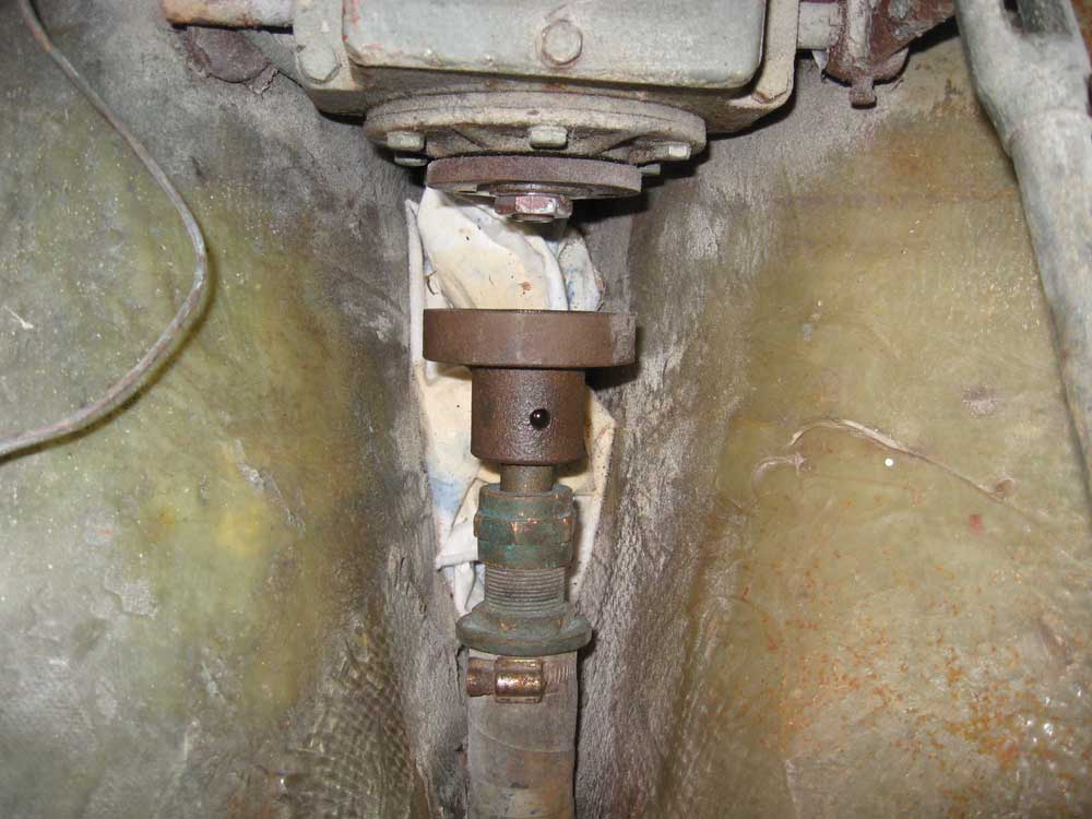
Also on my list was to address the running gear. The stuffing box was in shabby condition, with a well-worn and tired hose, rusty clamps, and was completely loose on the stern tube--that is, the hose spun when the shaft was turned. It was time to replace this key component. Additionally, the Cutless bearing was worn and sloppy and required replacement. To fix these items, I had to remove the propeller and shaft. I used my puller to remove the propeller without too much trouble, and then turned to the shaft coupling, which was well-rusted and looked like it would be a challenge to remove. Earlier in the project, knowing this removal was ahead of me, I'd doused the coupling and bolts liberally with penetrating oil. This enabled the three coupling bolts to come off without any difficulty. Then, I removed the single set screw from the coupling, which also came out without a fight. |
 |
|
The only way I was going to get the coupling off the shaft was with the tried-and-true, if tedious, method of using long bolts and a center insert (usually a deep socket) to pull the shaft off the coupling bit by bit. Of course, I didn't have any 3/8-24 (fine thread) bolts on hand, which was the thread size required for the tapped holes on the transmission coupling flange, so I couldn't begin this removal process immediately; I ordered the necessary bolts, along with some other supplies I'd be needing shortly, for tomorrow, and doused the coupling and shaft again with more penetrating solvent. |
 |
|
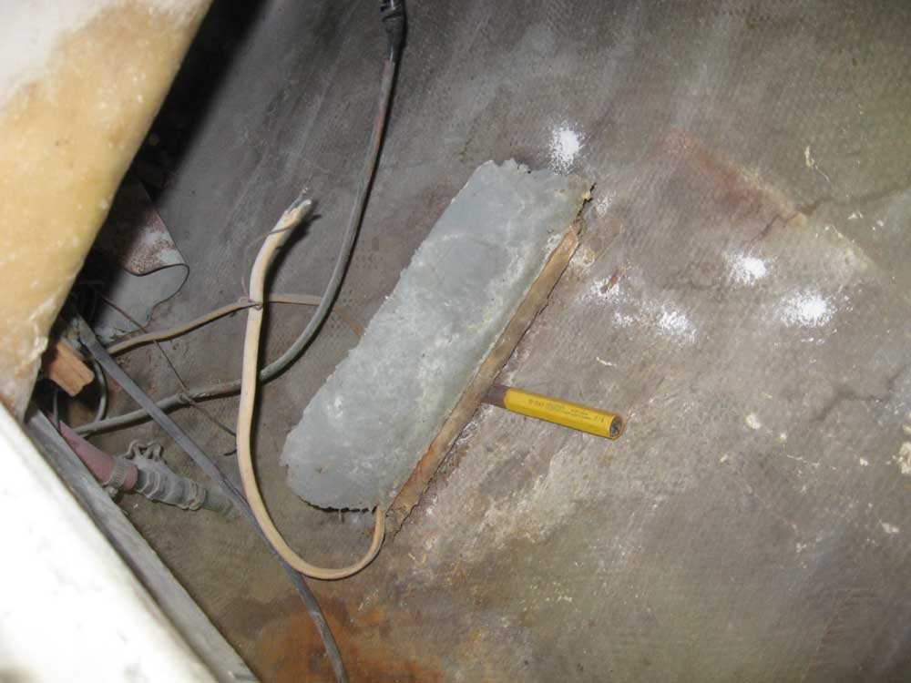
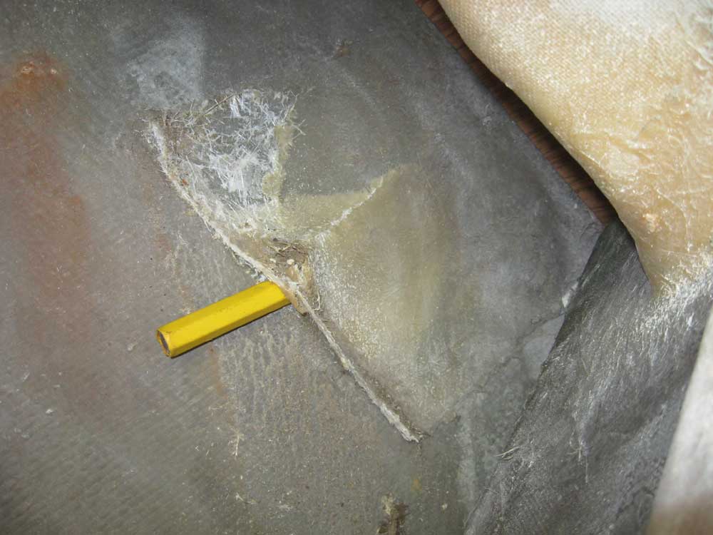
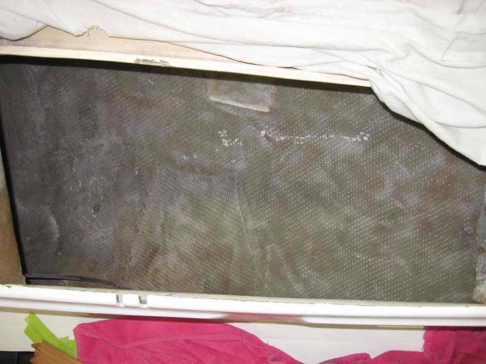
The boat required a new gasoline tank, so my next task was to look into the options available and consider how to proceed. First, though, I removed the old tabbing that had secured the original tank; it peeled easily away from the hull with a cold chisel and a little persuasion. Afterwards, I ground the tabbing remains and the hull inside the locker to smooth and clean up the surfaces, and cleaned up the resulting dust. |
 |
|
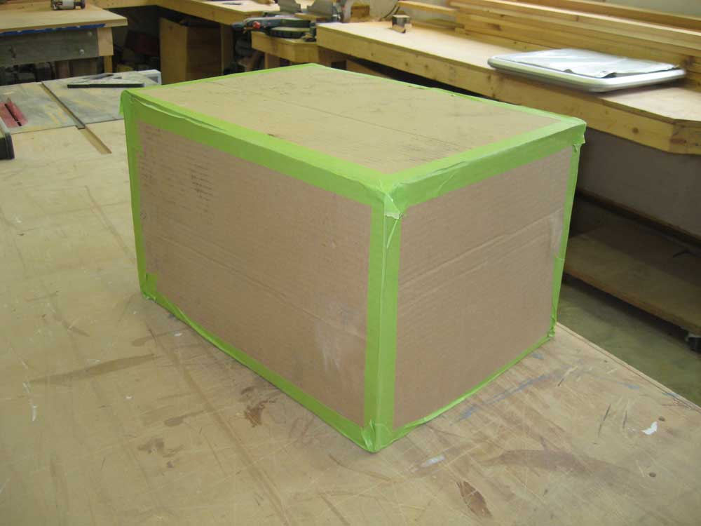
Given the small size of the locker opening, and the contours of the space within, the options were extremely limited, at least as far as stock plastic tanks were concerned. I found a few stock tanks with dimensions that might work, and after checking the measurements against the opening, chose one of the tanks and built a rough cardboard mockup to see if it would fit. As it happened, the dimensions were a lot tighter than I'd hoped, and considering that the stock tank of these dimensions also featured a molded fill neck that protruded above the maximum dimension of the tank, I wasn't sure that the tank would fit at all. There was another stock tank with a much lower height dimension (but wider and longer) that I thought might work, so I'd need to build another mockup tomorrow. But with the day wrapping up, I wanted to focus instead on one more epoxy installation that I could let cure overnight. |
 |
|
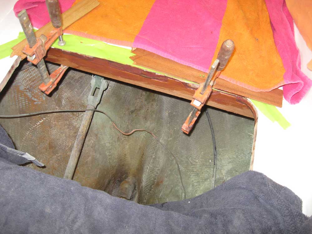
Earlier in the project, cutting the large hole in the cockpit sole for a new hatch had left the sole somewhat flexible when trod upon. To stiffen the sole, I cut a piece of mahogany to fit the aft side of the opening, and scribed it to more or less fit the shape of the bottom side of the sole, with its periodic glassed-in longitudinal stiffeners. Once I had an appropriate fit, I prepared the surfaces and epoxied the stiffener in place beneath the sole and flush with the opening, clamping it securely in place while the epoxy cured. |
 |
|
|
|