|
|
~MENU~ |
| Home |
| The Concept |
| The Boat |
| Bringing Her Home |
|
Weekly Progress Log |
|
Daysailor Projects |
| The Boat Barn |
| Resources |
| Other Sites |
| Email Tim |
|
|
|
Systems: Electrical System (Page 2) |
|
Rough Electrical Wiring Runs
|
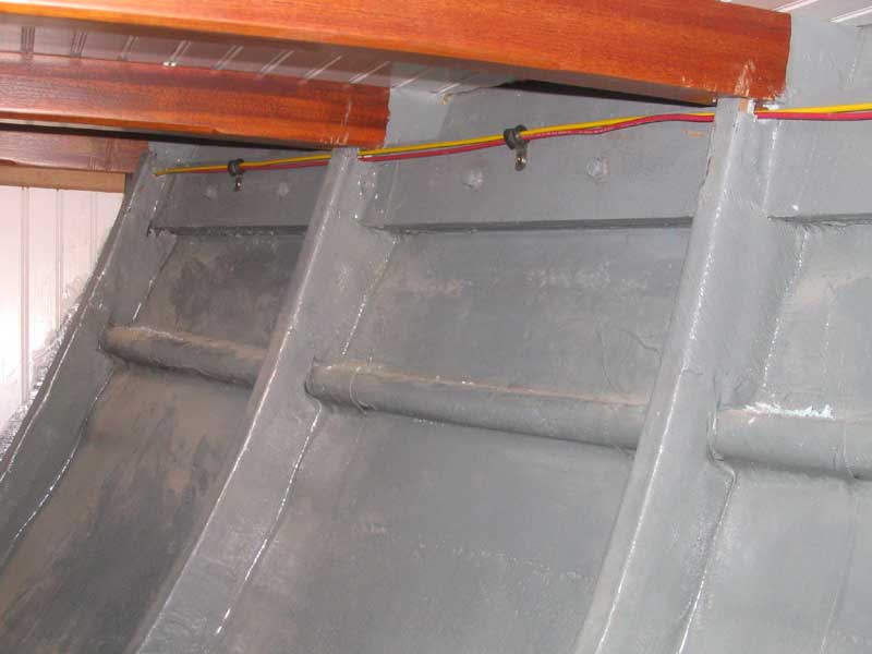
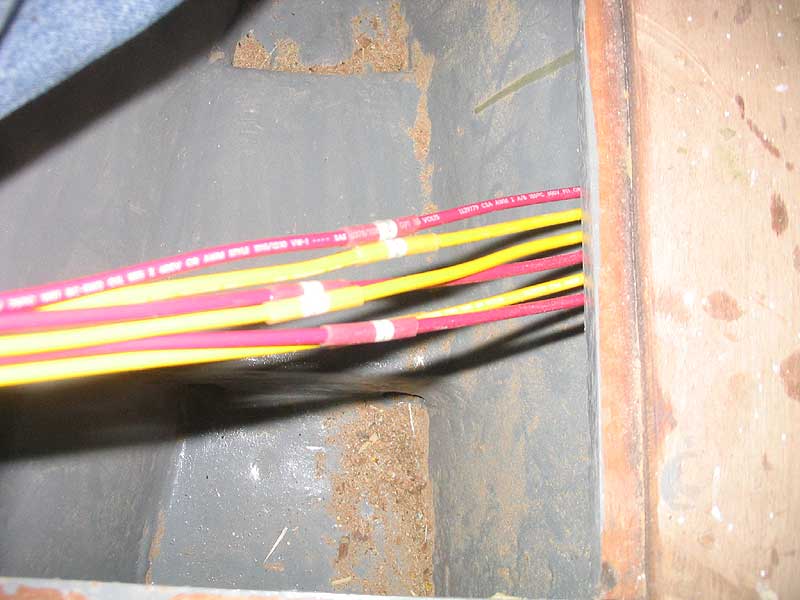
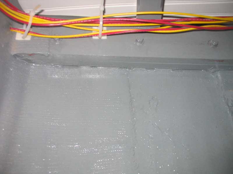 Next,
I ran three sets of wires from the panel area to the mast step in the
bilge, taking a convoluted path through the lockers to keep the wires
out of the way. With all three sets run, I secured them along the
way with cushion clamps. Unfortunately, at this stage of the game
I ran out of primary wire, having used some of my stock for another
project earlier in the week. Even this basic wiring had consumed
far more wire than I expected, using nearly 100' of each color for four
circuits. I had hoped to complete the bulk wiring at this point,
but with no wire in stock could not continue. Next,
I ran three sets of wires from the panel area to the mast step in the
bilge, taking a convoluted path through the lockers to keep the wires
out of the way. With all three sets run, I secured them along the
way with cushion clamps. Unfortunately, at this stage of the game
I ran out of primary wire, having used some of my stock for another
project earlier in the week. Even this basic wiring had consumed
far more wire than I expected, using nearly 100' of each color for four
circuits. I had hoped to complete the bulk wiring at this point,
but with no wire in stock could not continue.
|
 Once more wire
arrived, I continued with the basic wiring runs. First, I located
the four interior light fixtures, and drilled mounting and wiring holes;
I left the fixtures off for now, so that they would not be damaged
during construction. Once more wire
arrived, I continued with the basic wiring runs. First, I located
the four interior light fixtures, and drilled mounting and wiring holes;
I left the fixtures off for now, so that they would not be damaged
during construction. |
|
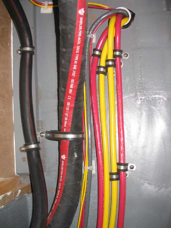
Next, I ran the wire pairs to each fixture; I dislike common grounds and continuous feeds, so ran separate cables to each fixture location. To reach the fixtures on the port side of the cabin, opposite the panel location, I ran the wires down through the engine room, carefully securing them along the way. I left plenty of extra cable for now. |
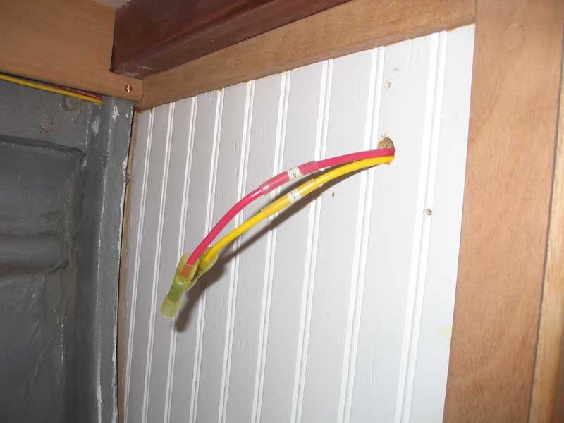
 I continued by running a pair of wires to the stern light area, leaving
plenty of extra in the lazarette since the fixture was not yet
installed. To pull the wires aft meant feeding them through the
one inaccessible area of the boat--outboard of the cockpit sides beneath
the sidedeck, in the short area aft of the aftermost bulkhead. To
get the wires through here, I first had to feed a wire snake through to
the transom from the engine room, then pull a messenger line, and
finally use the line to pull the wires through. The process went
smoothly, but illustrates the significant time commitment required for
so many of these jobs. I continued by running a pair of wires to the stern light area, leaving
plenty of extra in the lazarette since the fixture was not yet
installed. To pull the wires aft meant feeding them through the
one inaccessible area of the boat--outboard of the cockpit sides beneath
the sidedeck, in the short area aft of the aftermost bulkhead. To
get the wires through here, I first had to feed a wire snake through to
the transom from the engine room, then pull a messenger line, and
finally use the line to pull the wires through. The process went
smoothly, but illustrates the significant time commitment required for
so many of these jobs. |
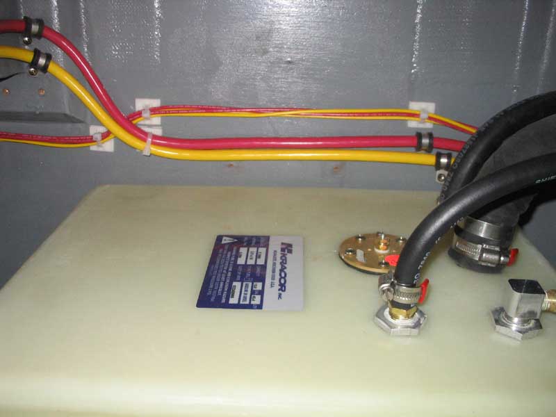
 I ran a 3-conductor sheathed cable (sold as bilge pump cable) to the
eventual electric bilge pump location in the forward engine room, and
back to the wiring area in the cabin. I ran a 3-conductor sheathed cable (sold as bilge pump cable) to the
eventual electric bilge pump location in the forward engine room, and
back to the wiring area in the cabin.
|
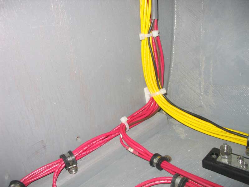
 Finally, with all the rough wiring
installed, I began cleaning up the installation by pulling the cables
tight and snugging up the various clamps and wire ties that I had
installed during the process. At the four light fixture locations
in the cabin, I installed the butt splice connectors on the ends in
preparation for final fixture installation later, and then connected all
the ground wires to the negative buss and even connected the cabin light
positive feeds, and running light positives, to small positive
distribution busses to prevent multiple wires from being attached to
single studs on the back of the main distribution panel. I used
adhesive-lined heat shrink ring terminals for all ends, and marked each
wire with a stick-on number, which I then covered with clear heat shrink
to ensure longevity. Finally, with all the rough wiring
installed, I began cleaning up the installation by pulling the cables
tight and snugging up the various clamps and wire ties that I had
installed during the process. At the four light fixture locations
in the cabin, I installed the butt splice connectors on the ends in
preparation for final fixture installation later, and then connected all
the ground wires to the negative buss and even connected the cabin light
positive feeds, and running light positives, to small positive
distribution busses to prevent multiple wires from being attached to
single studs on the back of the main distribution panel. I used
adhesive-lined heat shrink ring terminals for all ends, and marked each
wire with a stick-on number, which I then covered with clear heat shrink
to ensure longevity. |
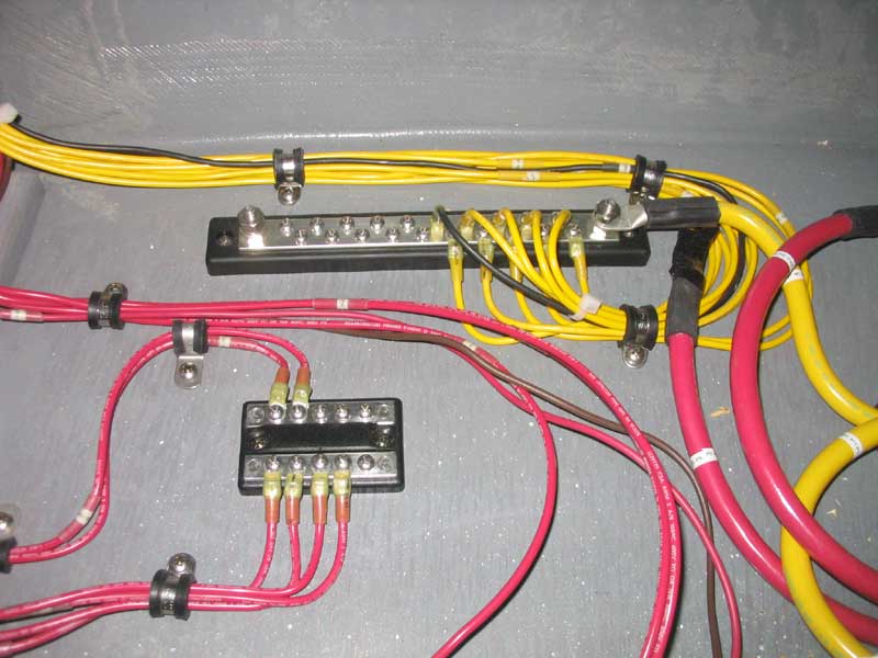 I obsessed over routing the wires neatly to the busses, but felt that
these efforts would pay off later in terms of ease of troubleshooting
and upgrading as needed. Later (see below for more), I added to
the wiring seen here as I completed the installation. I obsessed over routing the wires neatly to the busses, but felt that
these efforts would pay off later in terms of ease of troubleshooting
and upgrading as needed. Later (see below for more), I added to
the wiring seen here as I completed the installation. |
|
|
|
|
|
To begin, I built a pair of simple cleats that I secured inside the opening in the settee back to support the new panel. I created a recess deep enough to ensure that the panel switches and battery switch would be below the level of the opening when complete, and screwed the cleats in place through the settee back. |
|
Next, I cut a piece of thin plywood to shape, nibbling off the edges so that it could pass through the curved corners of the opening. It looked like it would be tight clearance for the height of the main service panel (with 8 circuit breakers), but I thought it would work. I laid out the panel to accommodate the main service panel, battery switch, and a bilge pump switch, and then cut the openings as needed. When I went to test-fit everything, though, I realized that there was no way I could make the panel arrangement work in its current configuration. I hoped to hinge the bottom edge for easy access, but the opening was too small to let the main panel swing through. Therefore, I had to enlarge the opening in the settee back and build a new, larger panel that would better accommodate everything. I painted the panel white, but didn't fuss over it too much. It seems that I do not have pictures of this process--sorry! |
|
After installing the various components in the backing panel, I set to work completing the wiring in the utility space behind the panel opening, connecting the battery cables to the switch and panel as needed, and finalizing the panel connections. I continued my efforts to keep the wiring extremely organized and neat, with an eye towards future troubleshooting ease. |
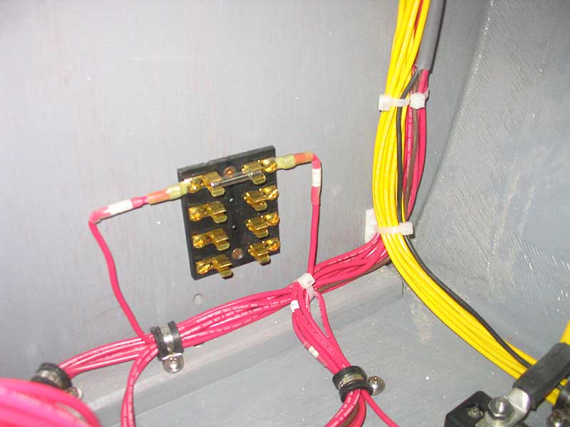
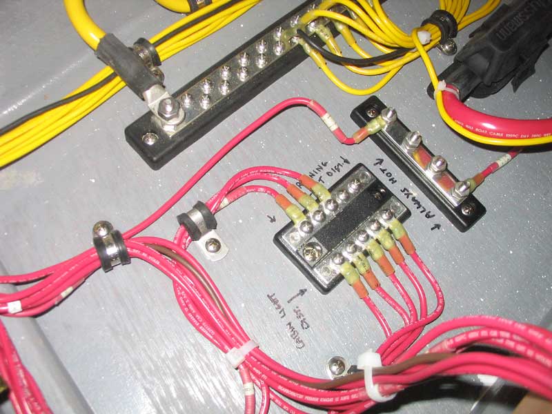 I
added a common buss to accommodate the multiple wires of the running
lights circuits and the cabin lights, so that only a single wire would
connect to the back of the circuit breaker on the panel. I also
added a 4-gang fuse block for ease of fusing the bilge pump circuit and
any future electronics that might be added. I
added a common buss to accommodate the multiple wires of the running
lights circuits and the cabin lights, so that only a single wire would
connect to the back of the circuit breaker on the panel. I also
added a 4-gang fuse block for ease of fusing the bilge pump circuit and
any future electronics that might be added. |
|
|
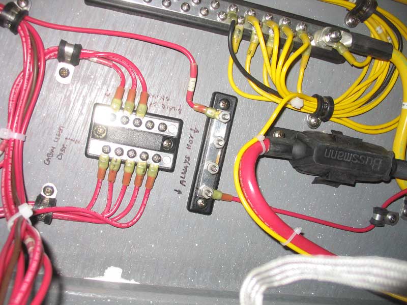 For
the bilge pump, I also added an always-hot buss that I connected to the
hot side of the battery switch. This would ensure that the bilge
pump would always operate, even when the main battery switch was turned
off. I also left room for future expansion as necessary. For
the bilge pump, I also added an always-hot buss that I connected to the
hot side of the battery switch. This would ensure that the bilge
pump would always operate, even when the main battery switch was turned
off. I also left room for future expansion as necessary. |
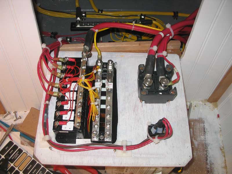 Finally,
I secured all the wiring into its final position, and tightened down any
remaining loose cable ties to secure the wiring in place. All that
remained to complete the wiring was to install the lights and other
fixtures as required. Finally,
I secured all the wiring into its final position, and tightened down any
remaining loose cable ties to secure the wiring in place. All that
remained to complete the wiring was to install the lights and other
fixtures as required. |
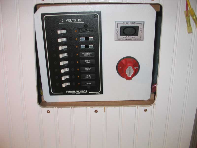 This photo shows the exterior of the panel; note that the panel is not
yet secured in the opening, but is simply resting in place for the time
being until I obtain the proper hinges and other hardware required. This photo shows the exterior of the panel; note that the panel is not
yet secured in the opening, but is simply resting in place for the time
being until I obtain the proper hinges and other hardware required. |
| Back to the Main Menu> |