
110 Cookson Lane | Whitefield, ME 04353 | 207-232-7600 | tim@lackeysailing.com
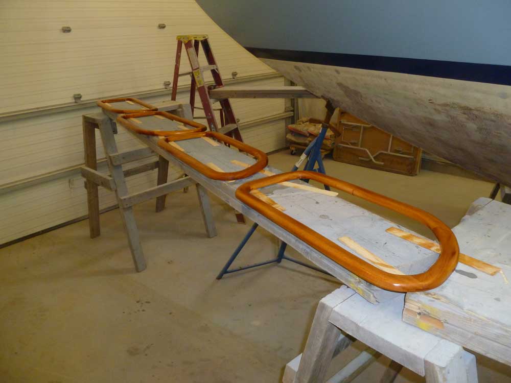
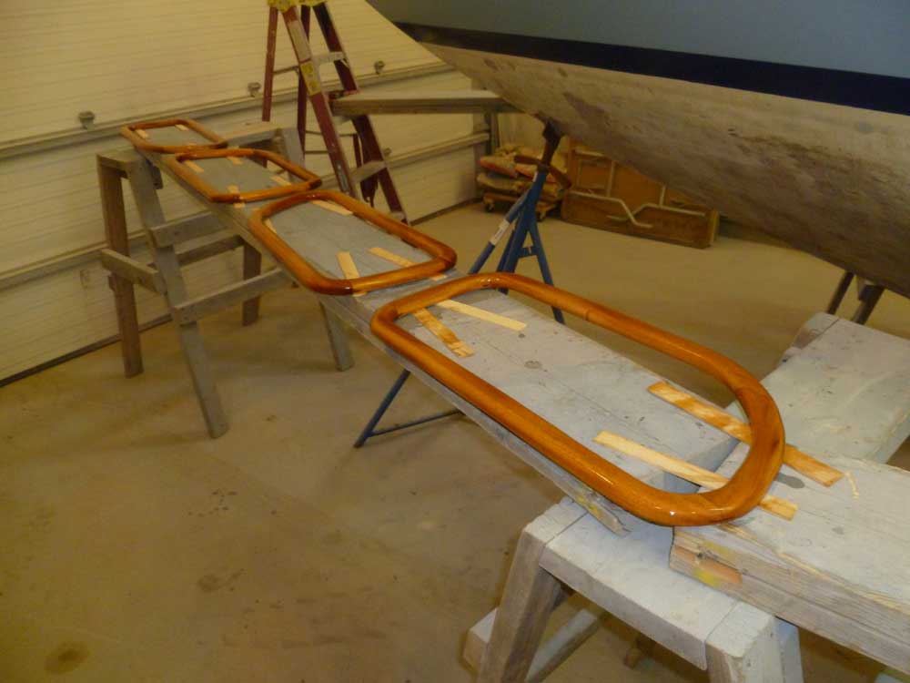
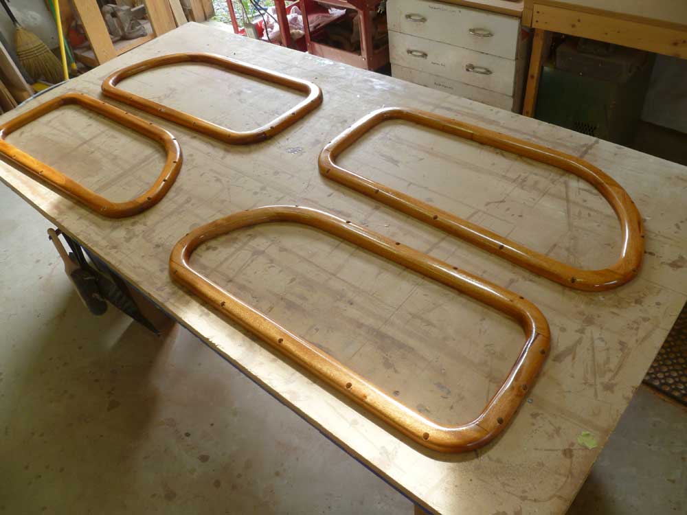
Over the weekend, I applied a couple coats of varnish to both sides of the new deadlight frames, preparing them for their installation in the near future.
Left: First coat
Right: Second coat
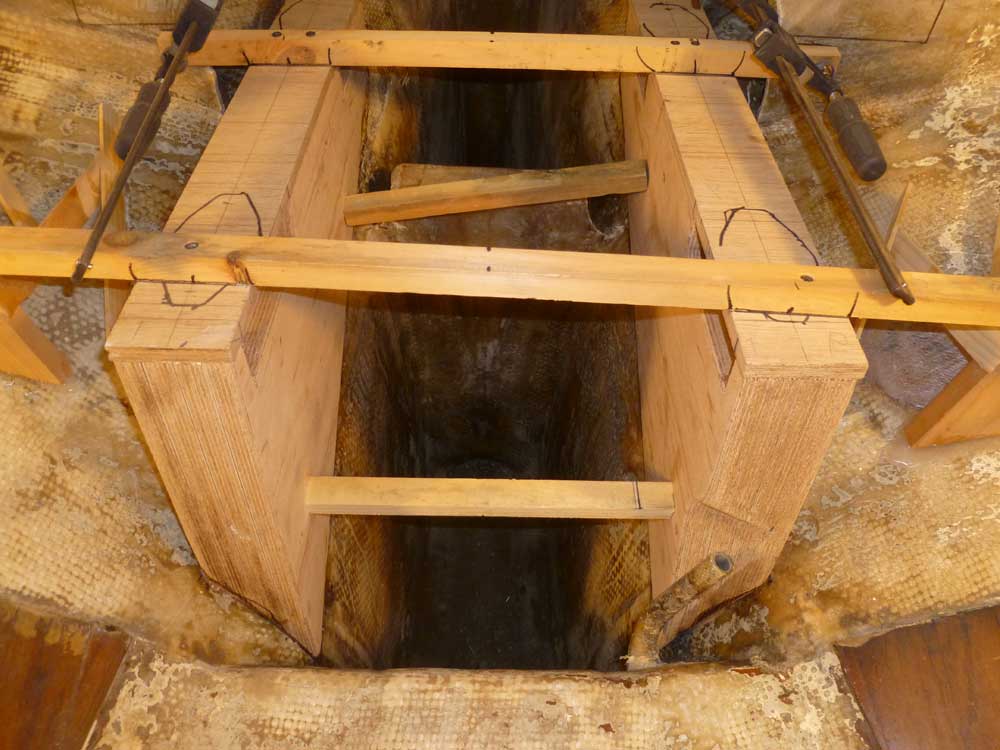
My initial focus was on the engine foundations. A quick test-fit late last week showed a need to fine-tune their shapes a bit so that I could properly position them on my reference marks, so I spent the first part of the day paring away portions of the foundations' bearing surfaces so that I could fit them closely to the hull. Various laminate bumps in the hull made themselves known as I continued the process, which was more time-consuming than I'd hoped, but was ultimately successful.
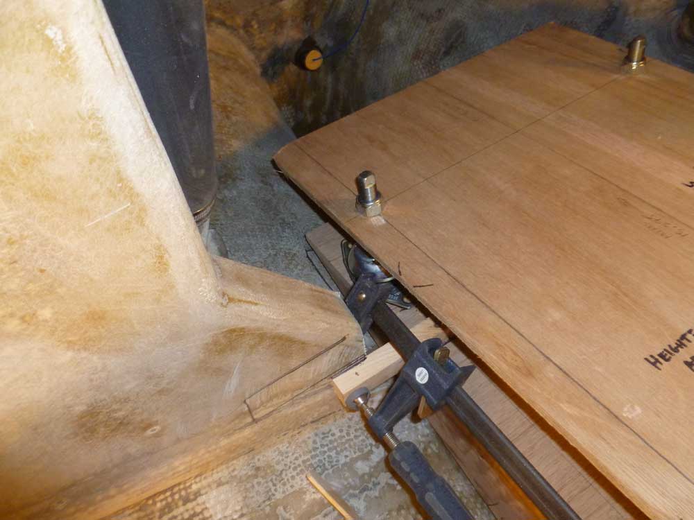
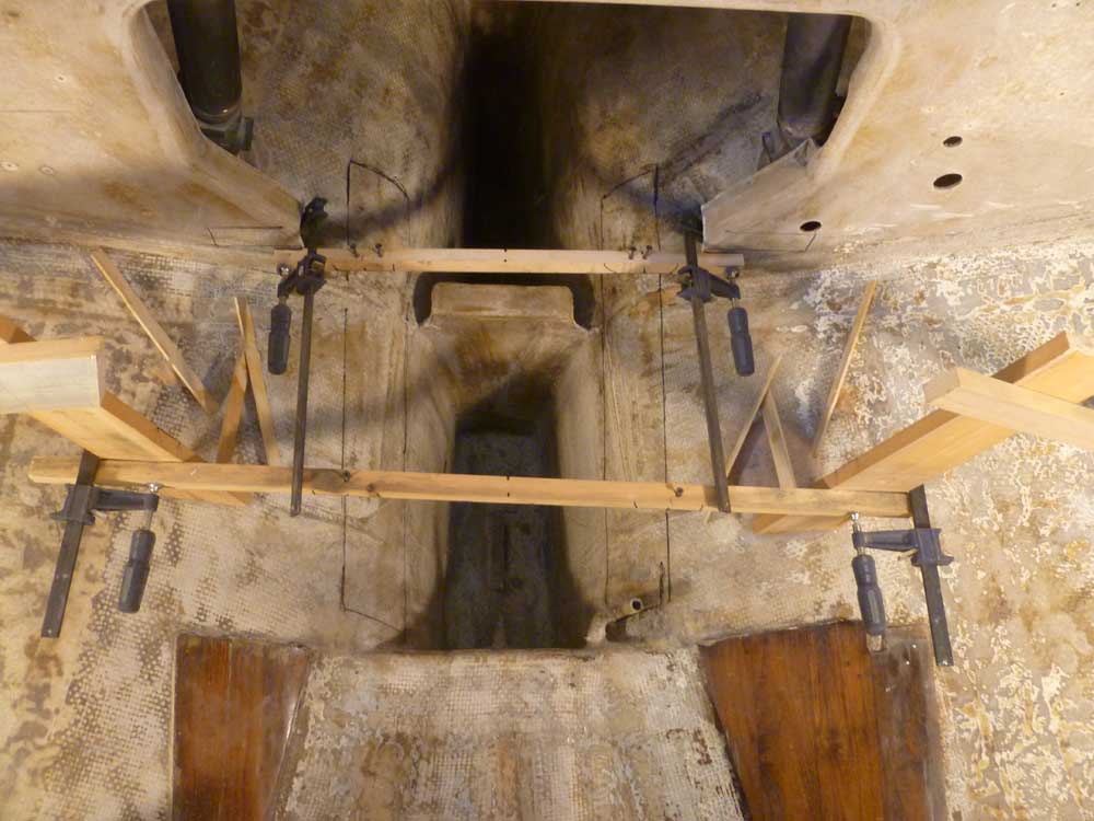
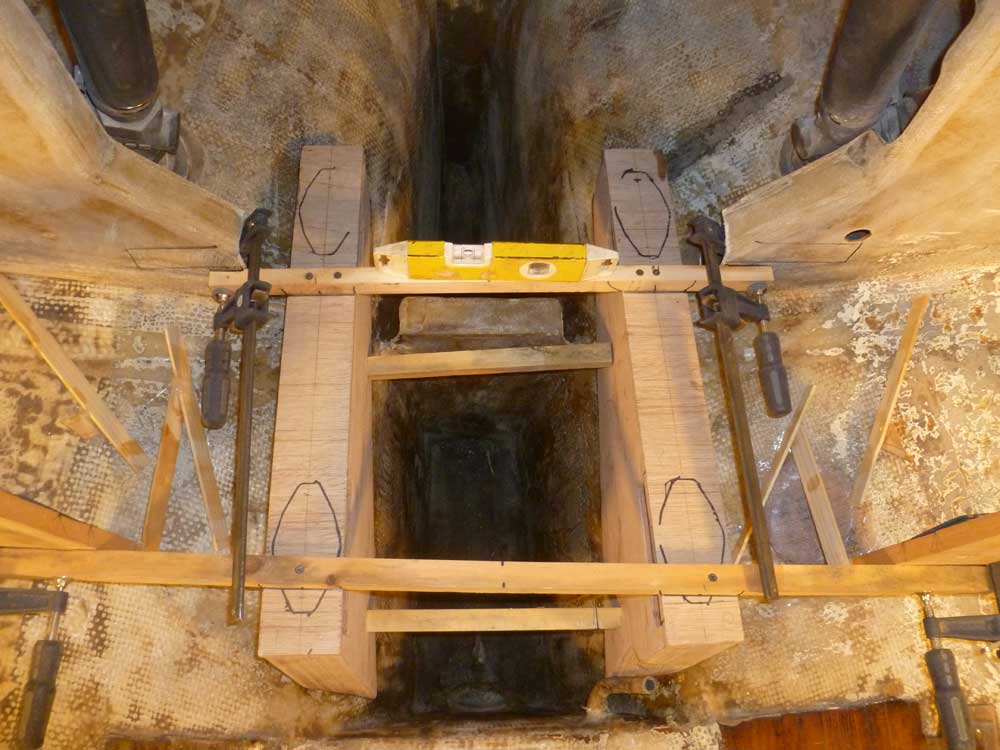
With the foundations temporarily secured in place with screws and a couple wooden braces, I double-checked the measurements to ensure the mounting centers were properly spaced (14.5" on center) and that the foundations were in the proper position according to the engine template. Note that in these photos, I was using the engine template only to check basic positioning of the foundations, and not to align the template with the shaft centerline string, as the position of my temporary horizontal braces prevented the forward mounts from landing in their proper position. I'd recheck the template against the centerline string again later in the installation process.
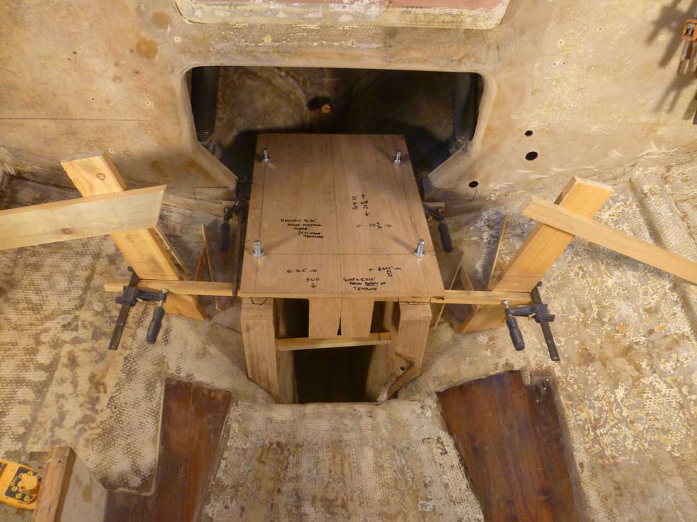
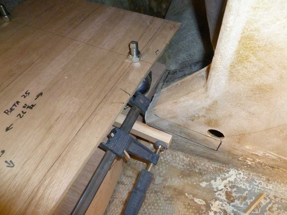
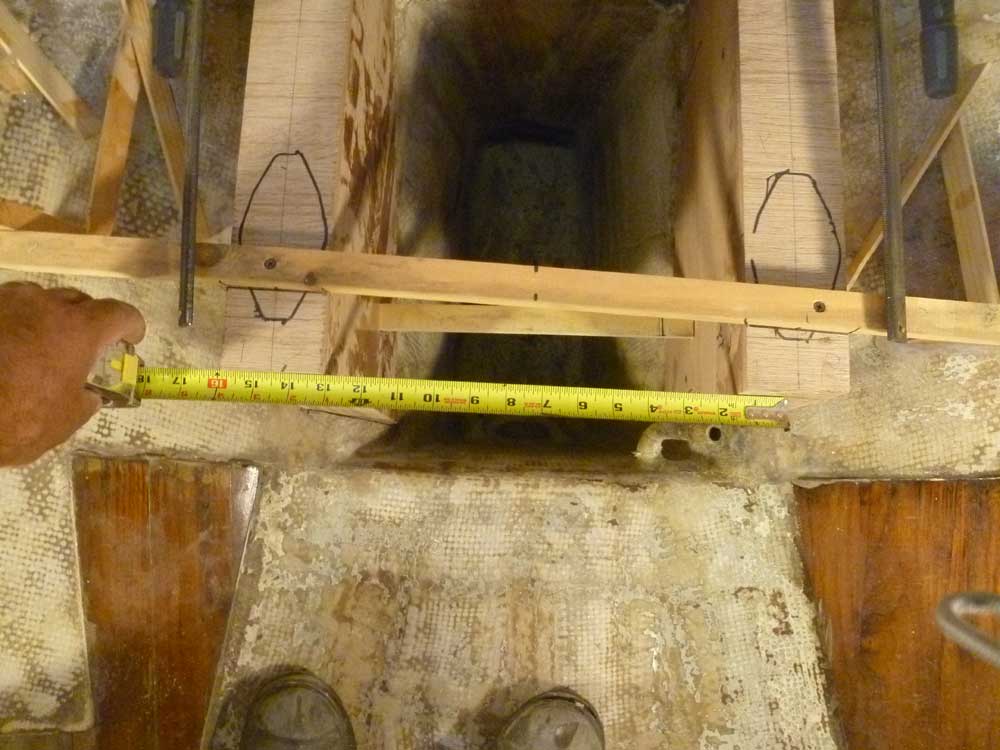
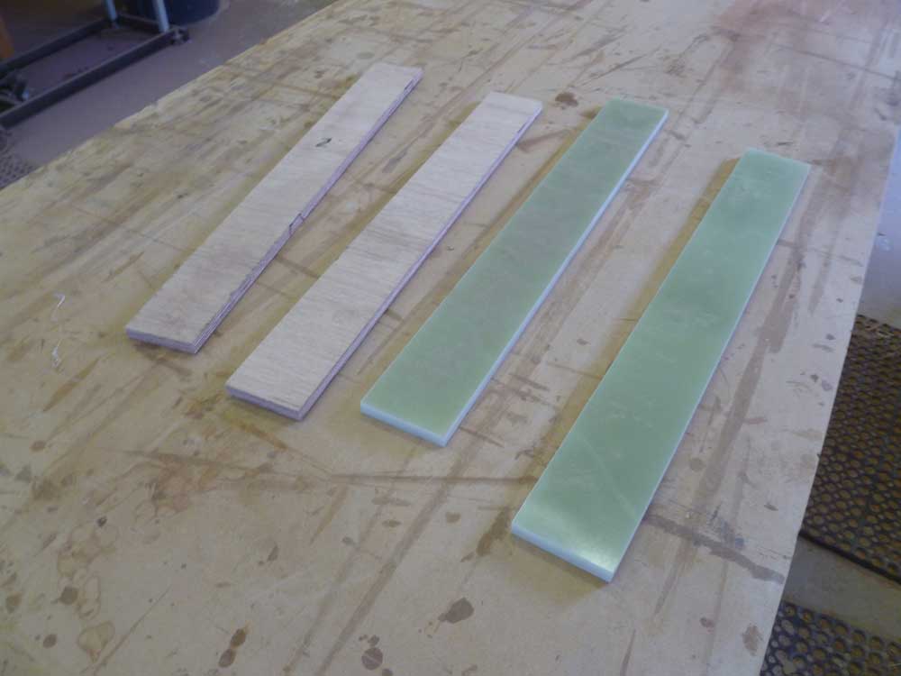
For the rough positioning and installation of the foundations, I relied on a 1/2" layer of plywood on the top surface of the foundations, which simulated what would be the final top surface: 1/2" G-10 fiberglass, a high-quality manufactured product of significant strength and density. I'd install the G-10 a bit later on, but for the moment its plywood stand-in made up the height difference and gave me a place to drive temporary screws to hold the foundations in place.
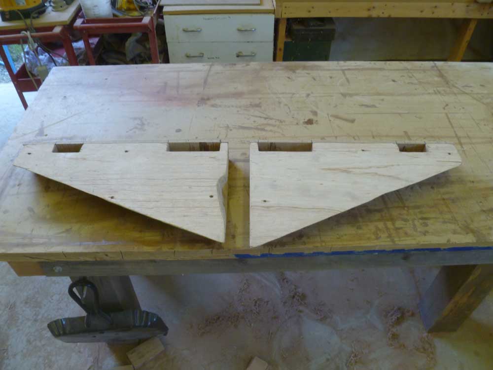
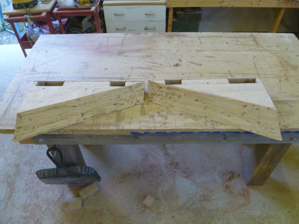
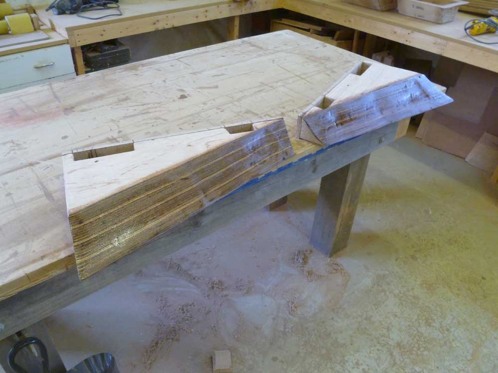
The reason I chose the G-10 for the top surface was so I could create pockets beneath the engine mount locations, allowing me to secure bolts, washers, and nuts through the fiberglass. To that end, once I had the foundations' shape fine-tuned, I cut openings in the top edge of the foundations in the appropriate locations; the G-10 would span these gaps, giving me the bolting arena. I removed the temporary plywood spacers from the top edge before beginning.
At the aft end, the tapered shape of the wooden foundation would make it difficult to install a through bolt and nut on the aftermost bolt location, so I created the opening only beneath the forward bolt on the after engine mounts; later, I'd drill and tap threads for machine screws in these two locations.
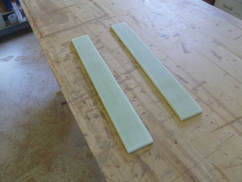
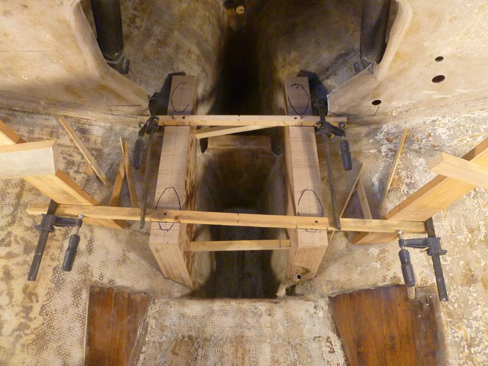
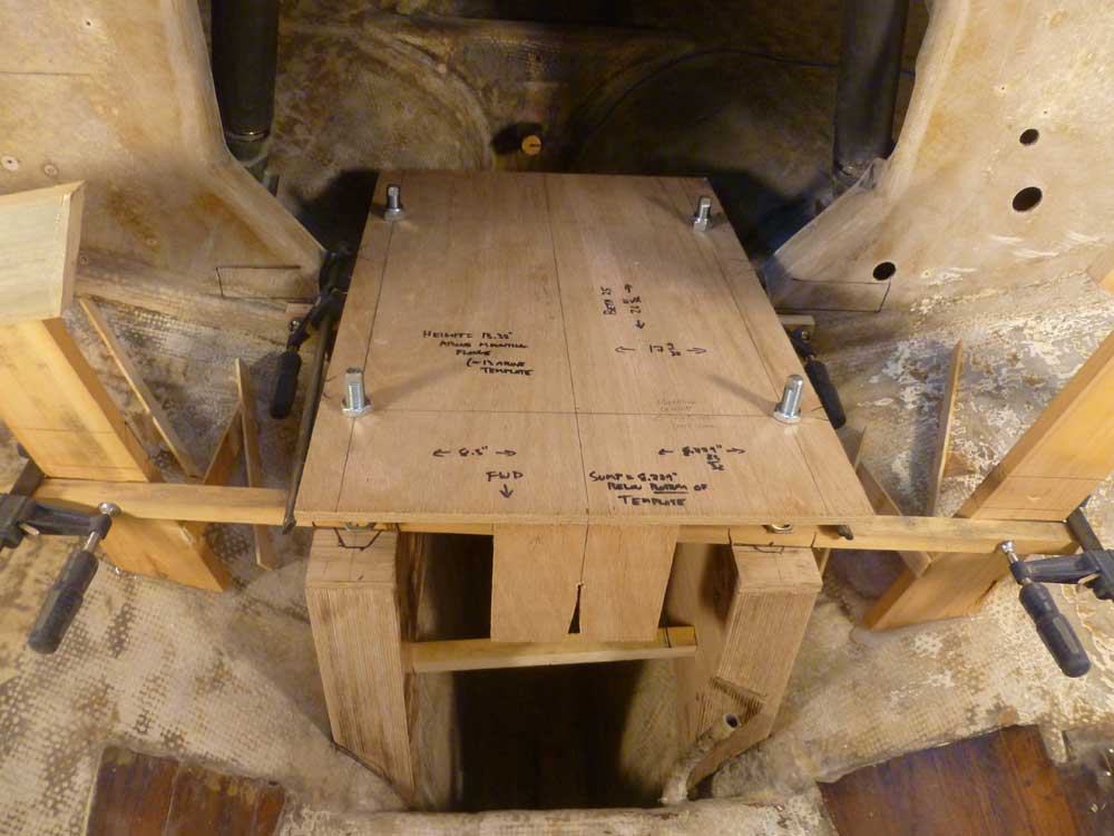
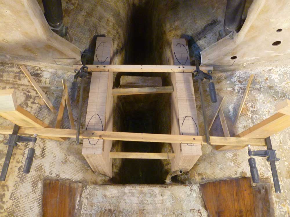
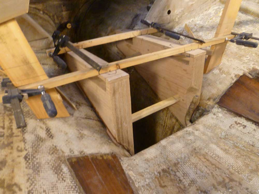
I sanded and lightly shaped the G-10 strips to prepare them for installation, but refrained from installing them till later. For now, it was time to tack the foundations themselves in place. After sanding and shaping the foundations, I reinstalled the plywood top spacers with dabs of hot glue, then coated the bearing surfaces of the foundations with epoxy as a pre-treatment. I cleaned up the mounting surfaces in the boat, then secured the foundations in place in a bed of thickened epoxy adhesive, enough to tack them securely in place, though I'd install more later on as part of the final installation.
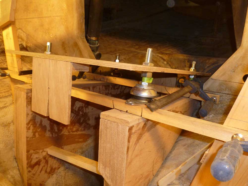
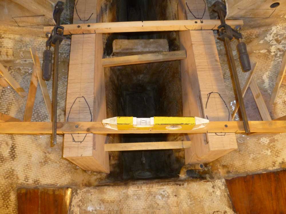
To hold the foundations securely, I screwed through the horizontal braces above the foundations, and installed cross braces between the foundations to press them tightly into their proper position and alignment. Once more, I checked alignment and measurements to ensure they were in the right place.
Note: the forward horizontal brace is not square to the foundations because of the positioning of my rough support structures on each side. This angle can make the foundations look out of kilter, but it's the brace, not the foundations.
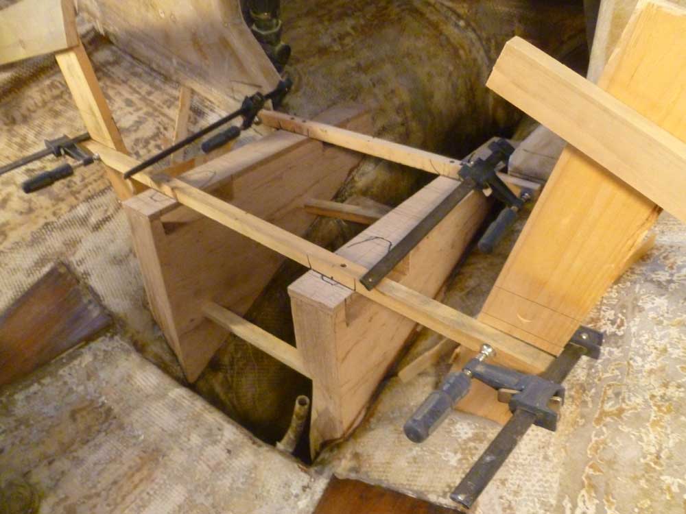
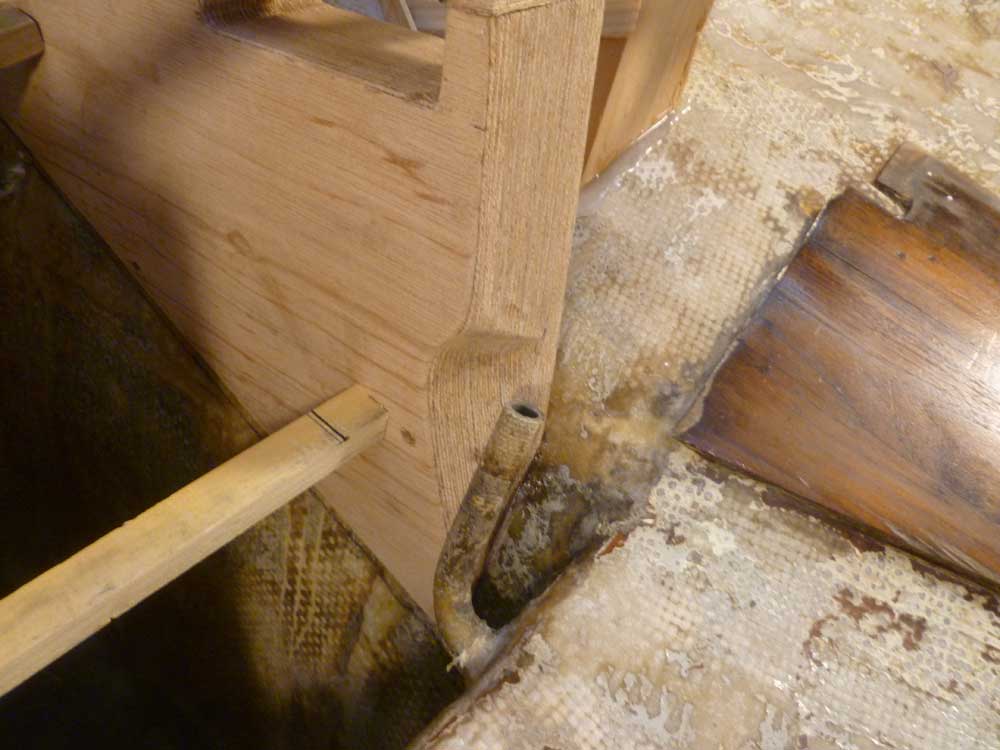
During layout and fitting, I'd shaped the forward edge of the port foundation to provide clearance around a hose connection stemming from the keel-mounted water tank.
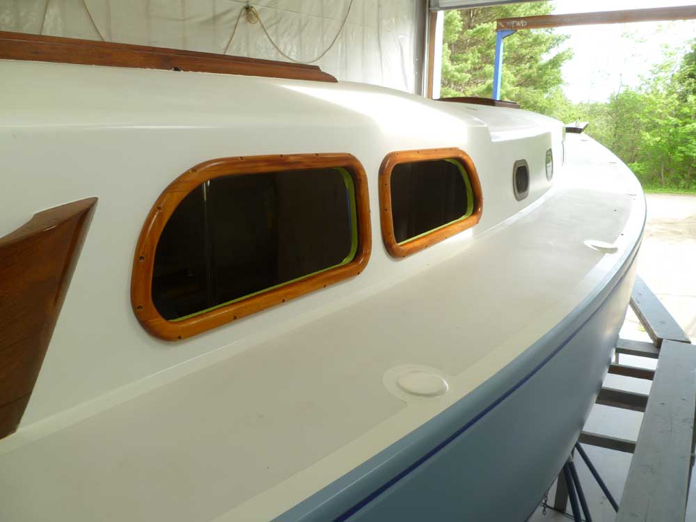
I left the foundations alone to cure for the rest of the day, and turned to the deadlights once more. With the frames pre-varnished, my next step was to lay out and drill for the mounting screws. I hated to drill holes through the frames, but it was the only way to secure them.
For each frame, I laid out screw patterns around the edge as needed to secure the frames tightly in place. The overlap of the frames on the cabin sides themselves was fairly minimal, about 1/2" only, so I had to keep the screw holes fairly close to the edge, while still allowing room for 3/8" counterbores and bungs to hide the screws. More overlap would have been nice from an installation standpoint, but to have made the frames wider would have looked awkward and bulky.
I drilled the pilot holes at the drill press, then drilled 3/8" counterbores to recess and hide the screws with bungs after final installation. This was a surprisingly fussy process given the rounded edges of the frames.
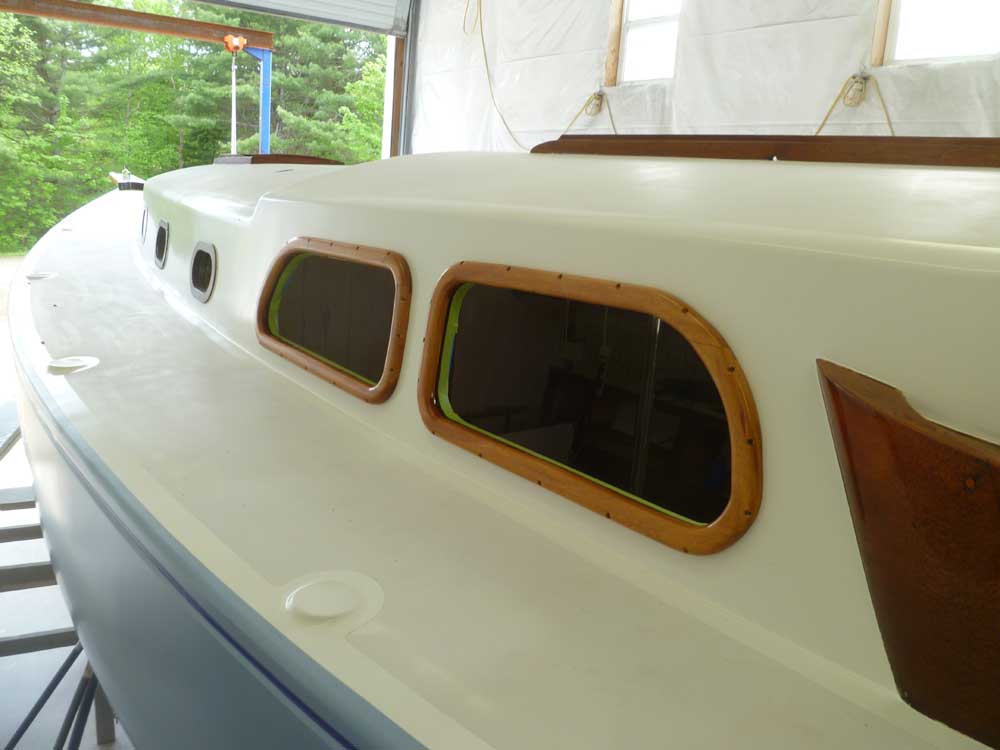
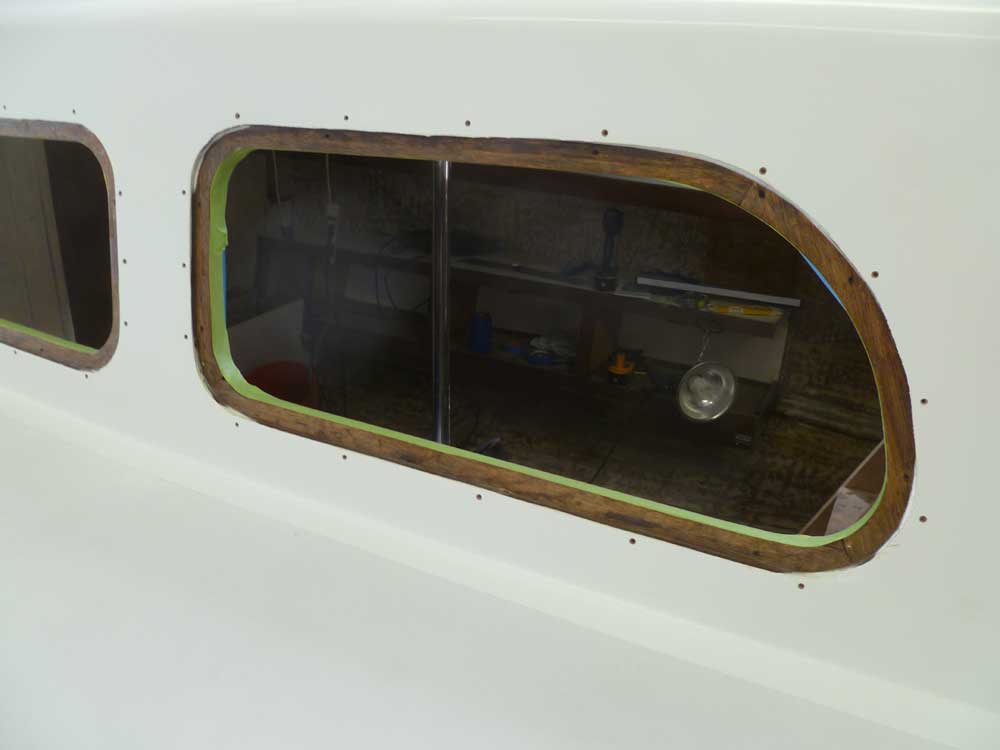
Finally, I dry-fit each frame, secured each with a pair of temporary screws, and drilled pilot holes in the cabin side for the mounting screws. After removing the frames, I milled small countersinks at each screw location to provide a place for a little extra sealant right where it would be needed most. I masked off the varnished interior deadlight trim, and awaited the dawn of a new day before beginning the final installation process.
Total Time Billed on This Job Today: 9 hours
(including varnish time over the weekend)