
110 Cookson Lane | Whitefield, ME 04353 | 207-232-7600 | tim@lackeysailing.com
Snow Lily | Thursday, May 30, 2013
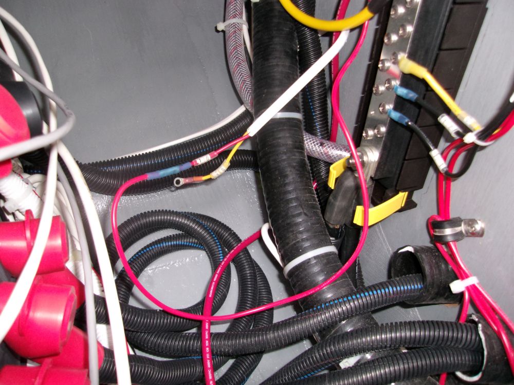
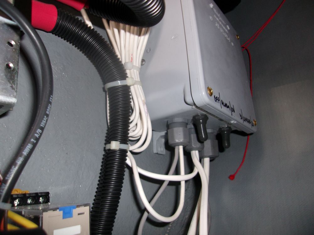
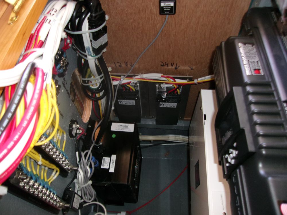
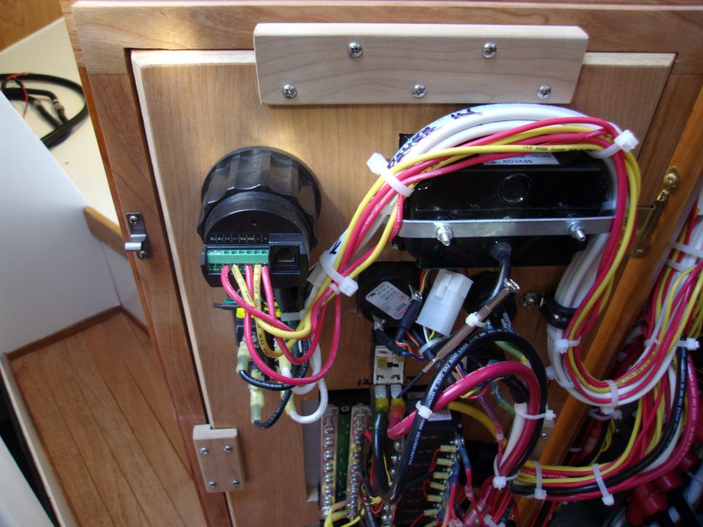
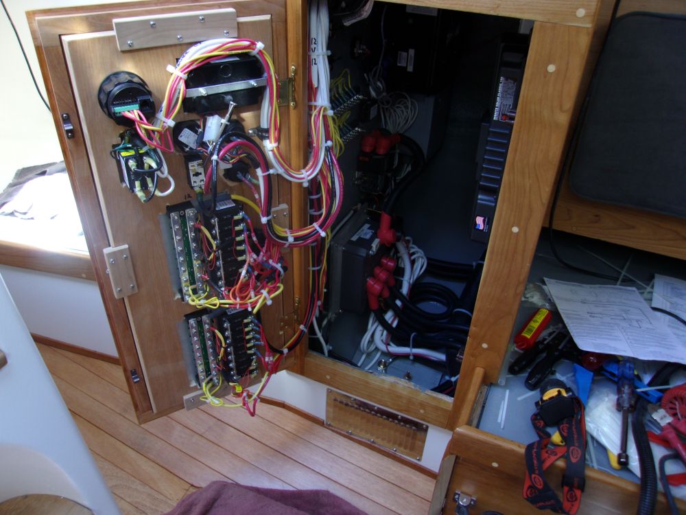
The wiring related to the BMS (battery management system) turned out to be largely straightforward, more a matter of leading various pre-made wiring harnesses to their correct destinations. Most of the heart of the system was contained in a separate box, which I did not have to open or deal with; I'd installed this box during an earlier work session, leaving only the wires to run based on a comprehensive wiring diagram. Among the wiring harnesses leading from the box was the main power supply, a low-voltage audible alarm, some sort of thing that connected to the shore power charger, Bluetooth module to allow wireless interface with a computer, and an additional shunt (with built-in wiring) to handle the current-sensing requirements.
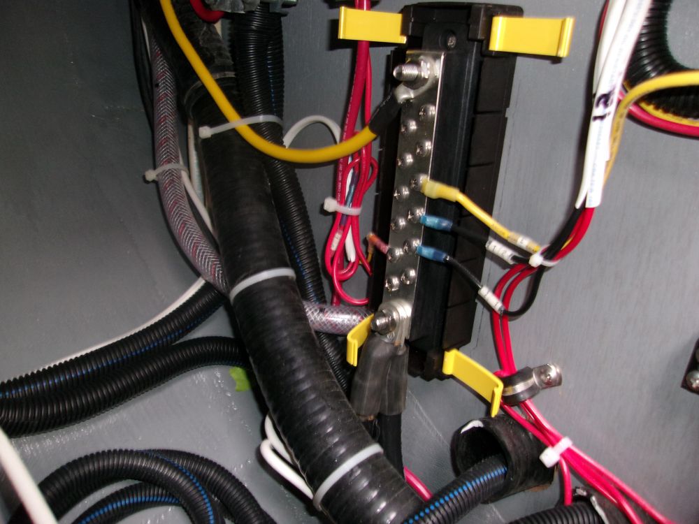
To begin, I connected the positive and negative power feeds, leading off the 48V distribution box and negative buss; these leads led to a separate 48V - 12V converter within the sealed BMS junction box.
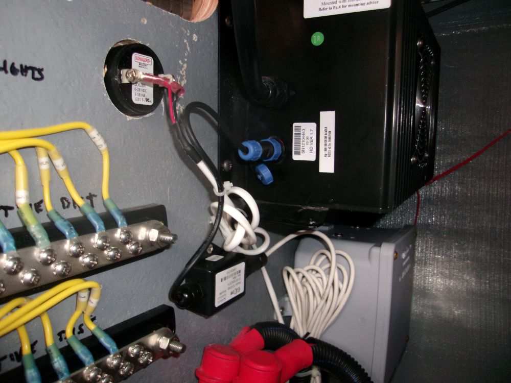
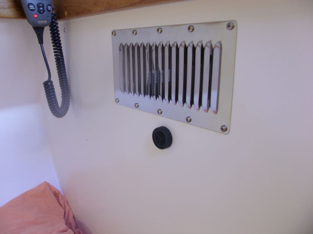
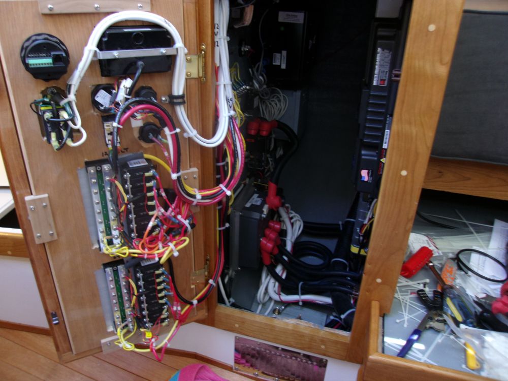
There wasn't really room in the electrical locker door to install the new alarm buzzer (there was already one there for some other part of the system), so instead I chose to mount it on the aft bulkhead of the locker, facing the quarterberth. because the alarm buzzer was designed for thin sheet metal panels, with only a small area of threads available for the securing nut, I had to use a large drill bit to bore out the fiberglass and plywood coring from the inside of the locker, therefore allowing me to install the buzzer through just the outer fiberglass skin.
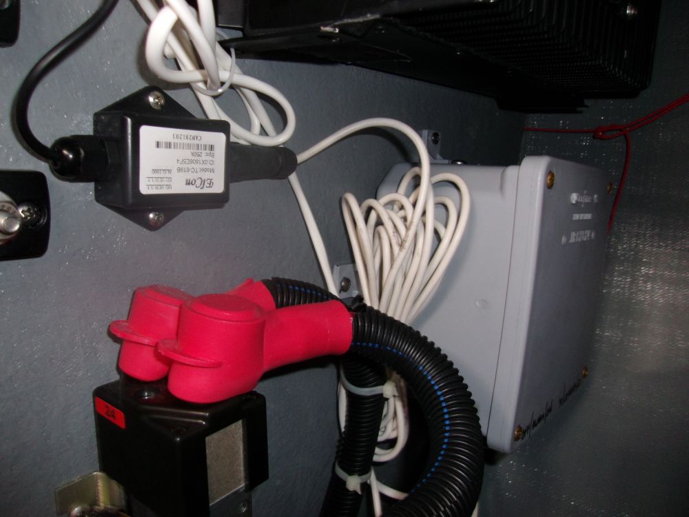
At the same time, I connected another harness to the shore power charger with a pre-made connector. this lead had at first confused me, as I wasn't immediately sure where this little box and connector were to go (they weren't on the wiring diagram and I hadn't immediately noticed any receptacles awaiting this sort of connection port), but it became clear soon enough when I noticed the covered port on the charger. Logic is a wonderful thing.

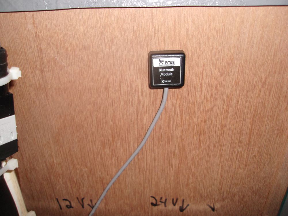
The Bluetooth module was self-adhesive, and I chose to mount it on the underside of the nav table top, where it was out of the way but hopefully in a good position to beam its little signal wherever it was needed.
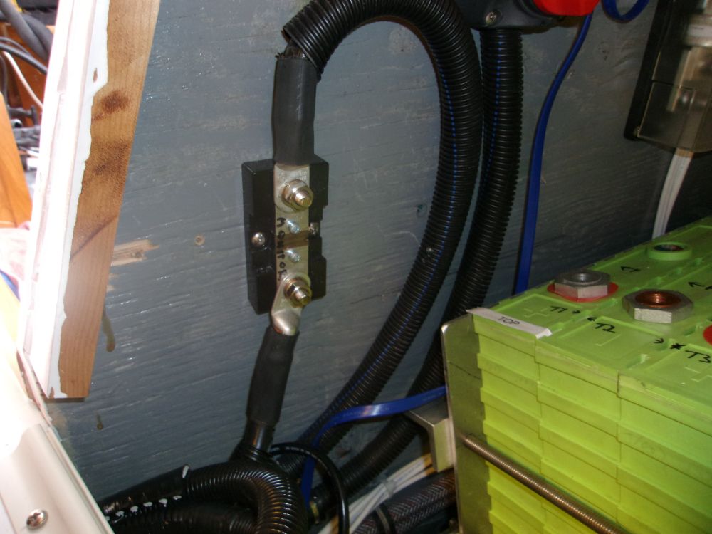
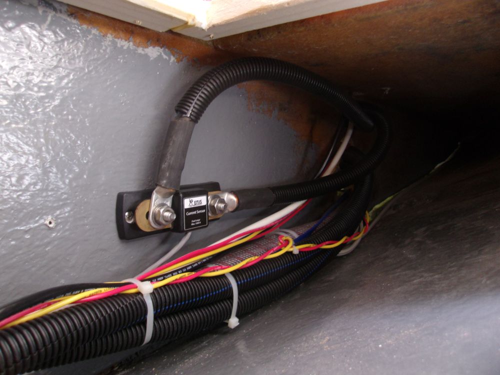
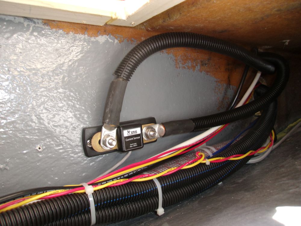
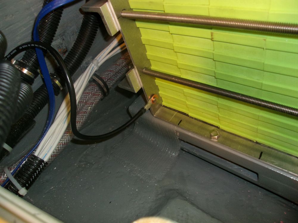
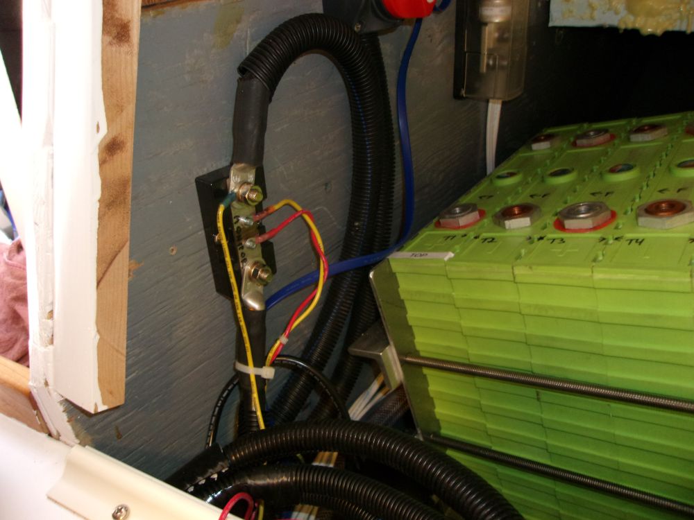
The built-in wiring and current-sensing module to the new shunt wasn't long enough to allow me to mount the shunt in the batter compartment, so instead I mounted it as close as I could (i.e. at the extent of the current-sensing wires), inside the wiring chase beneath the quarterberth. Then, I built and connected 2/0 black battery cables between the new shunt and an existing shunt (for a separate battery monitor) already in the compartment, and a final length of cable from the BMS shunt to the eventual connection at the negative terminal of the battery bank. I left the cable disconnected for now, as there was more work to do on the batteries before I could make final connections.
Meanwhile, I led an additional wiring harness (pre-made) from the electrical locker (originating in the BMS junction box) to the battery compartment. These harnesses carried the sensor wires required for the fancy BMS system that would monitor each battery cell individually, and for which additional components I'd soon be installing on the batteries themselves. For now, I just left the cables and harnesses loose in the compartment pending final connection.

The wiring schematic indicated ground wires (not negative) leading from the motor controller and the battery box to the Dynaplate, so I installed these cables accordingly.
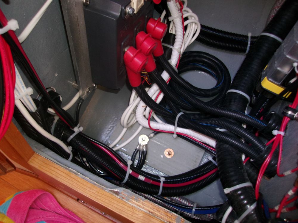
The owner had specified and ordered 48V - 110V inverter, required for minimal AC power needs like a computer, and while the inverter had been backordered and was not yet on hand I could make up some of the wiring in advance. To allow on-off operation of the inverter, I'd installed a rocker switch in the electrical panel, and now I led the 48V positive and negative leads to one side of the switch. Once it arrived, the new inverter would go in the one remaining space--jealously guarded specifically for this purpose--in the locker, and I'd make up the final wiring connections then.
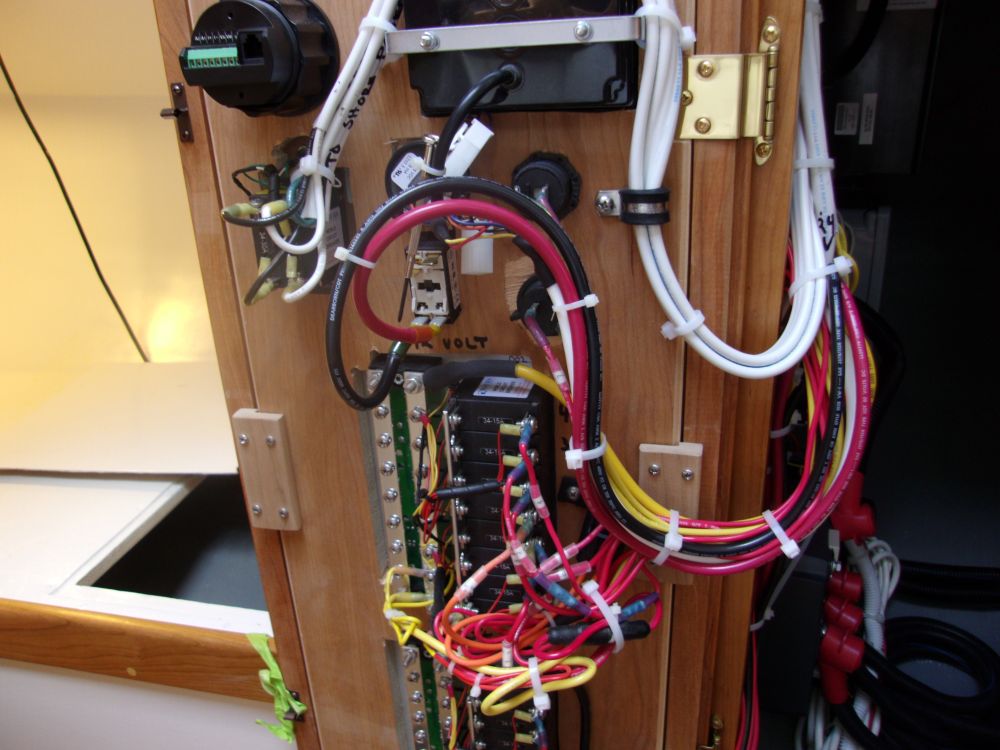
Though it was essentially superseded by the new BMS system, the original plan for the batteries had included a separate battery monitor, which I'd installed in the electrical panel long before, and a shunt for which I'd installed in the battery compartment. Now I made up the wiring as required for this monitor.
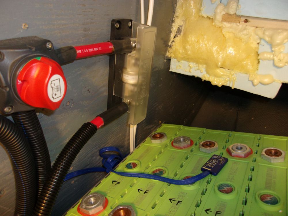
With my last length of red 2/0 cable, I made up the lead from the main fuse to the battery positive, leaving it disconnected from the batteries for now.
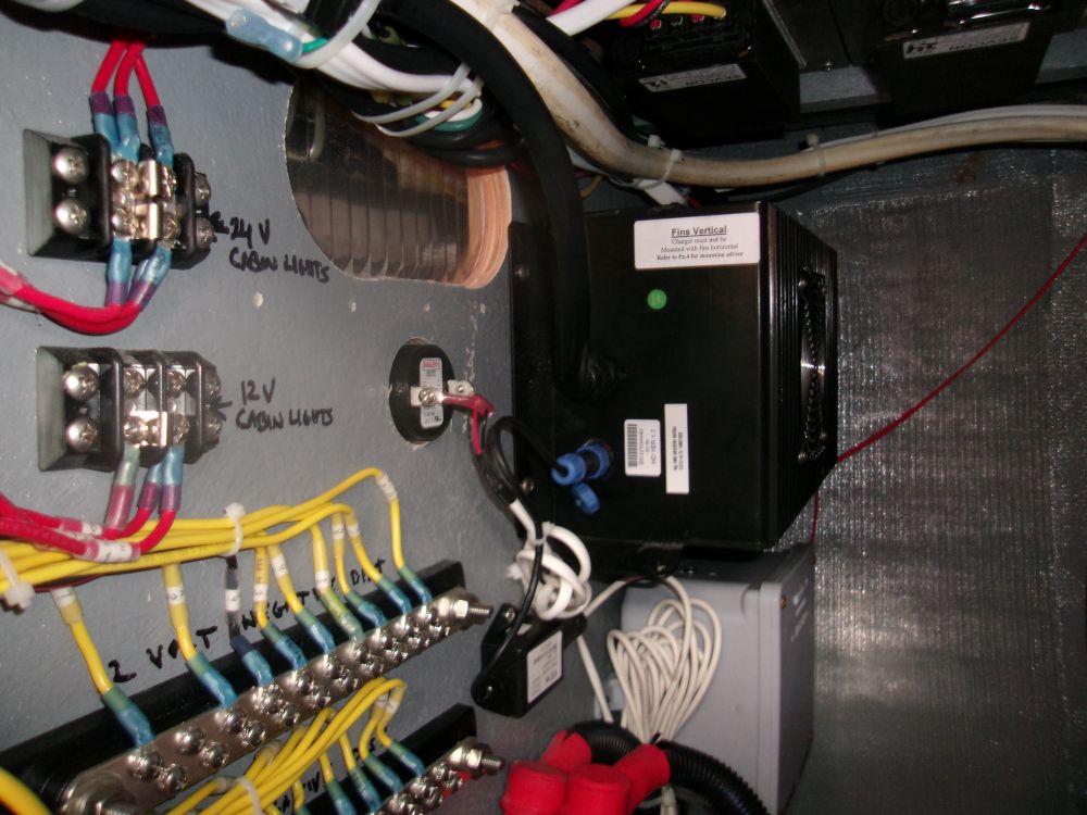
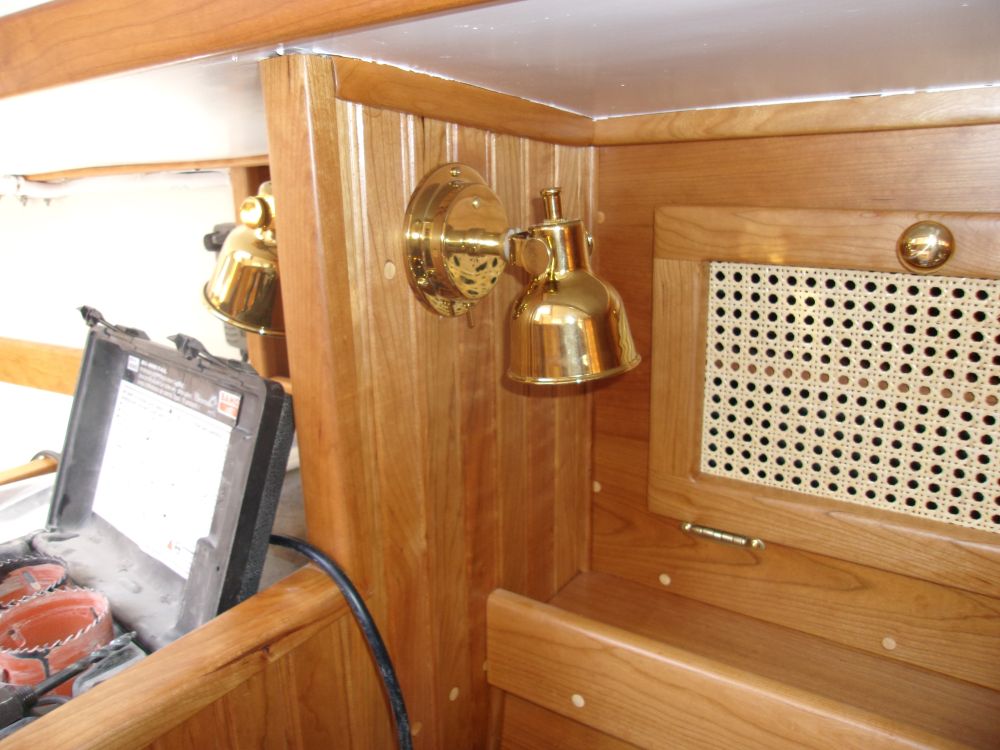
Finally, I installed the last 24V interior lamp, which had arrived earlier in the day from the owner. I'd pre-wired the location for the lamp, though at the time of wiring I thought it would end up being a 12V lamp. So after installing the lamp, I simply moved the corresponding wires from the 12V busses to the nearby 24V ones.
Total Time on This Job Today: 8.25 hours