|
|
~MENU~ |
| Home |
| The Concept |
| The Boat |
| Bringing Her Home |
|
Weekly Progress Log |
|
Daysailor Projects |
| The Boat Barn |
| Resources |
| Other Sites |
| Email Tim |
|
|
|
Systems: Electrical System |
| Batteries and Battery Cables
|
|
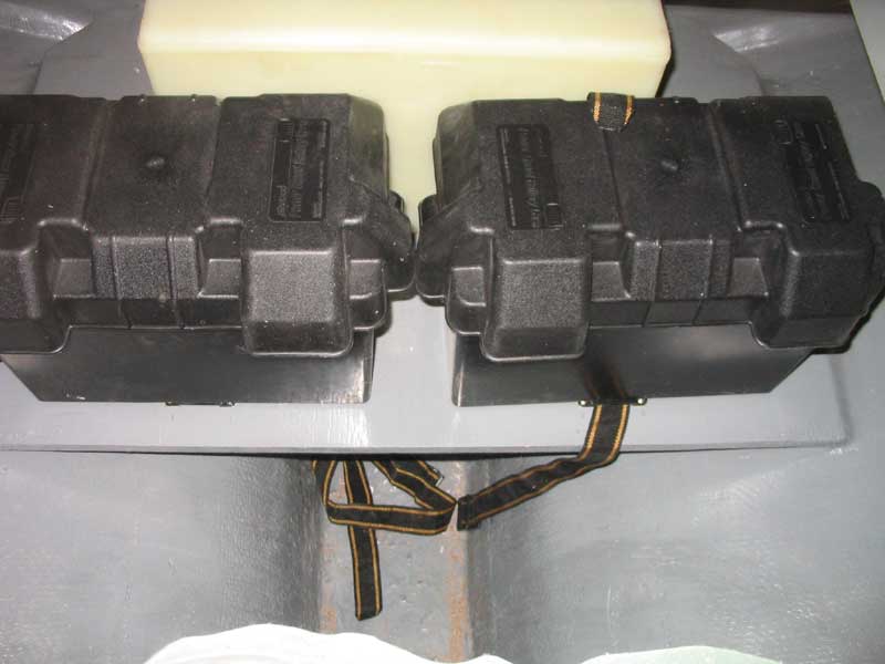
With the boxes installed, I continued by lugging two new Group 27 batteries up on deck and into the boxes. I planned a very simple electrical system, with the two batteries simply wired in parallel and no complex measures for starting battery isolation and so forth. Since the mission of the boat is so basic, and there will be little call for electrical power on board other than for basic lighting and engine starting, I saw no reason to complicate things. |
 Next,
I determined the general location of my interior electrical panel, which
would also house a basic on-off battery switch. With that location
figured out, I could begin running the battery cables. Next,
I determined the general location of my interior electrical panel, which
would also house a basic on-off battery switch. With that location
figured out, I could begin running the battery cables.I needed four cables running between the engine room and the interior of the boat (to the panel area): positive and negative distribution, power from the switch to the starter motor, and the main ground. I began with the two longest cables, which ran from the panel to the engine ground and starter motor. I used #2 battery cable in red and yellow. |
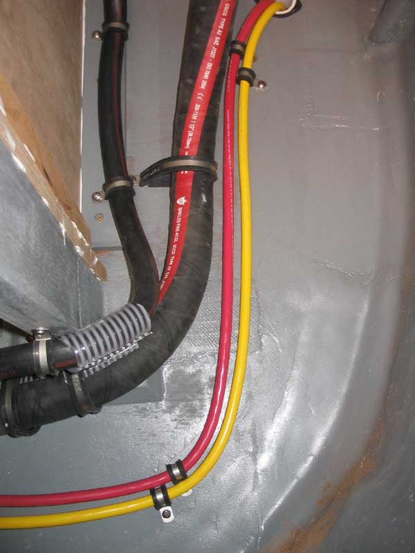 I
began by drilling a 2" hole through the bulkhead between the engine room
and the cabin, up beneath the sidedeck and inside one of the settee
lockers (starboard side). I lined the hole with a short length of
white hose that I held in place with cable ties on each side of the
bulkhead; this provided chafe protection where the cables and wires
would run through the bulkhead. I
began by drilling a 2" hole through the bulkhead between the engine room
and the cabin, up beneath the sidedeck and inside one of the settee
lockers (starboard side). I lined the hole with a short length of
white hose that I held in place with cable ties on each side of the
bulkhead; this provided chafe protection where the cables and wires
would run through the bulkhead. |
|
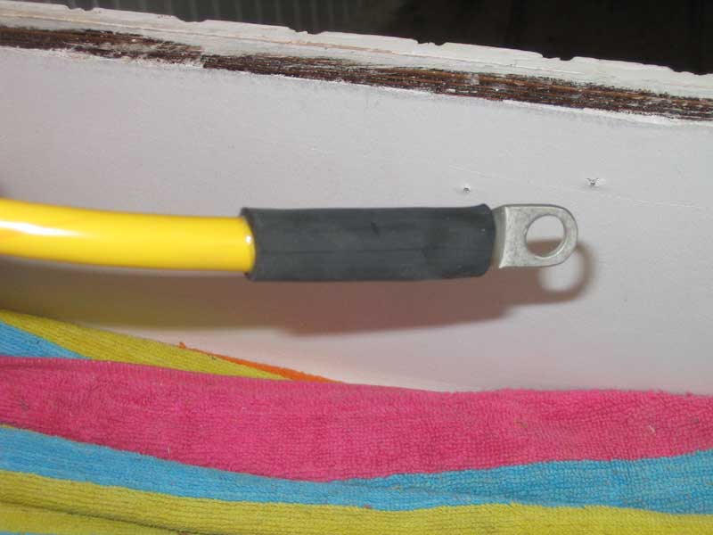
T 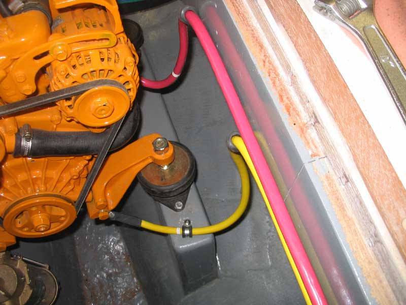 hen,
I ran the cables through, pulling lots of extra. Once I had the
cables run roughly to their ultimate connection points on the engine
(ground to the forwardmost engine mount bracket, and the power to the
starter motor), I stripped the cable ends and installed tinned copper
lugs, which I then covered with heavy-duty adhesive-lined heat shrink
tubing. hen,
I ran the cables through, pulling lots of extra. Once I had the
cables run roughly to their ultimate connection points on the engine
(ground to the forwardmost engine mount bracket, and the power to the
starter motor), I stripped the cable ends and installed tinned copper
lugs, which I then covered with heavy-duty adhesive-lined heat shrink
tubing. |
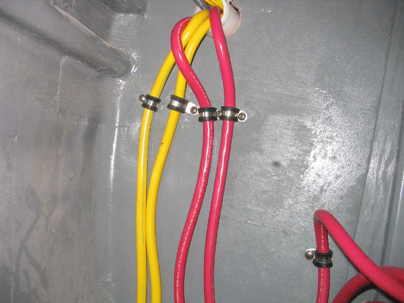
 Connecting
the new terminals temporarily to the studs as required, I then worked my
way backwards into the cabin, securing each cable along the way with
cushion clamps as required. The square corners required for a neat
installation consumed lots of cable, more than expected (of course).
Eventually, the cable was well secured in the engine room and up to the
bulkhead pass-through, and inside the boat I determined the final length
of the cables and cut the ends; then, I installed more tinned lugs of
the appropriate size (3/8" hole for the positive cable connection at the
battery switch, 5/16" for the negative cable to the negative
distribution bus). This seemingly basic process took a couple
hours to complete, and by then the day was over. Connecting
the new terminals temporarily to the studs as required, I then worked my
way backwards into the cabin, securing each cable along the way with
cushion clamps as required. The square corners required for a neat
installation consumed lots of cable, more than expected (of course).
Eventually, the cable was well secured in the engine room and up to the
bulkhead pass-through, and inside the boat I determined the final length
of the cables and cut the ends; then, I installed more tinned lugs of
the appropriate size (3/8" hole for the positive cable connection at the
battery switch, 5/16" for the negative cable to the negative
distribution bus). This seemingly basic process took a couple
hours to complete, and by then the day was over. |
 I continued the next morning by fabricating the
two remaining main battery cables: the cable running between the
battery and the negative distribution buss, located behind the eventual
panel location; and the main positive battery cable. I had just
enough cable remaining on the reels to complete these jobs. I continued the next morning by fabricating the
two remaining main battery cables: the cable running between the
battery and the negative distribution buss, located behind the eventual
panel location; and the main positive battery cable. I had just
enough cable remaining on the reels to complete these jobs. |
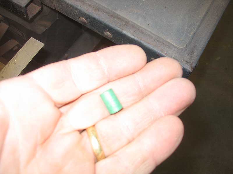 I chose some solder terminal connections for the battery ends. The
terminals were designed for use with pre-sized solder pellets, sold
according to the cable size. I was using #2AWG cable, so chose the
green pellets. The process was simple: I chose some solder terminal connections for the battery ends. The
terminals were designed for use with pre-sized solder pellets, sold
according to the cable size. I was using #2AWG cable, so chose the
green pellets. The process was simple: |
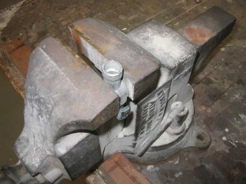
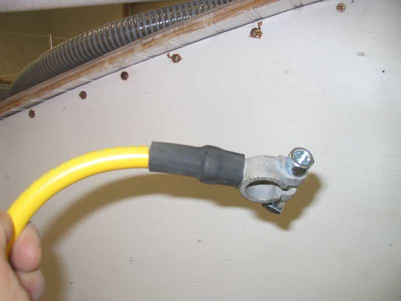
 First, clamp the terminal in a vise, and drop in the pellet. Then,
heat the terminal with a torch until the solder melts, and stick in the
cable end. To prepare the cable for this step, I first stripped
off about 3/4" of the insulation (the instructions called for 1", but
this was too much), and then applied some liquid flux (part of the
system) to the exposed wires. When the solder was melted, I pushed
the cable end into the liquid, completing the installation.
Finally, I covered the terminal and cable end with more of the
heavy-duty heat shrink tubing. First, clamp the terminal in a vise, and drop in the pellet. Then,
heat the terminal with a torch until the solder melts, and stick in the
cable end. To prepare the cable for this step, I first stripped
off about 3/4" of the insulation (the instructions called for 1", but
this was too much), and then applied some liquid flux (part of the
system) to the exposed wires. When the solder was melted, I pushed
the cable end into the liquid, completing the installation.
Finally, I covered the terminal and cable end with more of the
heavy-duty heat shrink tubing. |
 With the soldered connections complete, I ran the bitter ends of the
cables through the engine room and into the main wiring area behind the
starboard after settee, securing them with cushion clamps as I went.
Then, inside the cabin, I determined the cables' final lengths and
installed the appropriate crimped tinned copper battery lug terminals. With the soldered connections complete, I ran the bitter ends of the
cables through the engine room and into the main wiring area behind the
starboard after settee, securing them with cushion clamps as I went.
Then, inside the cabin, I determined the cables' final lengths and
installed the appropriate crimped tinned copper battery lug terminals. |
 I secured the cable running tot he negative distribution buss, but left
the remaining cables loose for now until I was ready to install them in
their appropriate locations, to be determined once I managed to build
the panel and finalize some other connections. I secured the cable running tot he negative distribution buss, but left
the remaining cables loose for now until I was ready to install them in
their appropriate locations, to be determined once I managed to build
the panel and finalize some other connections. |
 I
built two jumper cables required to connect the two batteries in
parallel, and installed them between the two batteries. Then, I
moved on to the final connections behind the main distribution panel in
the cabin, securing the battery cables to the battery switch,
distribution panel, and negative distribution buss as required. I
built two jumper cables required to connect the two batteries in
parallel, and installed them between the two batteries. Then, I
moved on to the final connections behind the main distribution panel in
the cabin, securing the battery cables to the battery switch,
distribution panel, and negative distribution buss as required. |
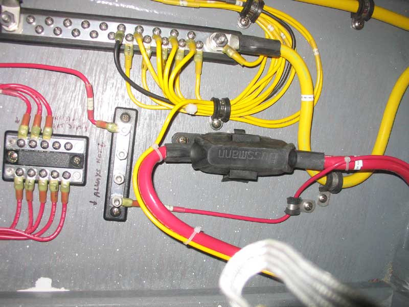 I
also added a 100-amp main fuse in the system as a safeguard.
Located between the battery switch and the electrical panel, this fuse
would serve as a catastrophic protection device for massive current
flows, should any circumstances arise that might create such a scenario. I
also added a 100-amp main fuse in the system as a safeguard.
Located between the battery switch and the electrical panel, this fuse
would serve as a catastrophic protection device for massive current
flows, should any circumstances arise that might create such a scenario. |
 As
before, I labeled all the cable ends and protected each connection with
heavy adhesive-lined heat shrink tubing, and secured the cables as
required with rubber cushion clamps. As
before, I labeled all the cable ends and protected each connection with
heavy adhesive-lined heat shrink tubing, and secured the cables as
required with rubber cushion clamps. |
|
Please click here to
go on to the primary wiring.>
|
| Back to the Main Menu> |