|
| |
|
From a Bare
Hull: Carlins
(Page 4)
|
|
Carlins: Final Installation
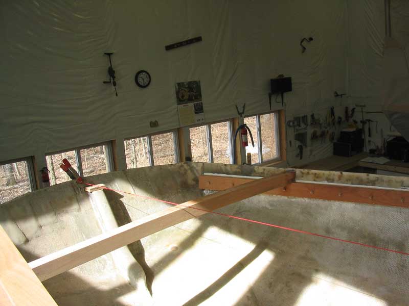
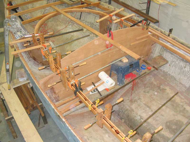
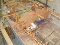
 Over the course of the next day and a part of
a second day, I completed the carlins' installation. Before I could
continue with the carlins, though, I had to install a full-width deck beam
at the after end of the cockpit, as the carlins were to intersect with and
attach to this beam. The day before, I had laminated this beam
section up, so I took several minutes to plane it smooth, then determine
its exact location in the hull. Once I had the location determined,
I cut and fit the beam in the same way that I did all the foredeck
beams earlier. Then I installed it in a bed of epoxy adhesive
with two bronze #14 x 3 screws, one at each end. Over the course of the next day and a part of
a second day, I completed the carlins' installation. Before I could
continue with the carlins, though, I had to install a full-width deck beam
at the after end of the cockpit, as the carlins were to intersect with and
attach to this beam. The day before, I had laminated this beam
section up, so I took several minutes to plane it smooth, then determine
its exact location in the hull. Once I had the location determined,
I cut and fit the beam in the same way that I did all the foredeck
beams earlier. Then I installed it in a bed of epoxy adhesive
with two bronze #14 x 3 screws, one at each end.
The
location I chose for this beam, 133" aft of the midships bulkhead, is
such that it lands aft of the tillerhead location on the imaginary cockpit
sole, and enough so as to allow the possibility of locating the tillerhead
at about cockpit seat level, which is often a more user-friendly location;
however, the beam is also located far enough forward of the transom that I
could choose to run the rudderpost all the way to deck level, as I have
discussed here and there in the past in the discussion forum
attached to this site. As it happened, this versatile beam location
was by happy coincidence, as I didn't make any particular
compromises for or against either tiller setup. Later in the
project, I will make the decision as to how to run the tiller and
rudderpost, but it was nice to know that I still had several viable
options. |
|
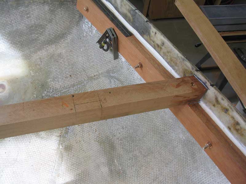
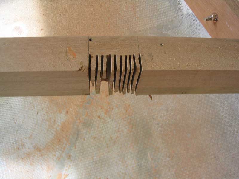
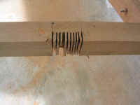
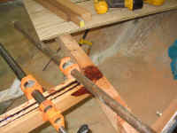
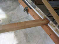 The carlins were to intersect with the aft
deck beam at a mortise, so I determined the location on each side and cut
the mortises to the appropriate shape, roughing out the cuts with my
circular saw and finishing with a chisel. I added an angled cut at the
outer edge to allow for the angle at which the curving carlin would
approach. The carlins were to intersect with the aft
deck beam at a mortise, so I determined the location on each side and cut
the mortises to the appropriate shape, roughing out the cuts with my
circular saw and finishing with a chisel. I added an angled cut at the
outer edge to allow for the angle at which the curving carlin would
approach.
|
|
|
|
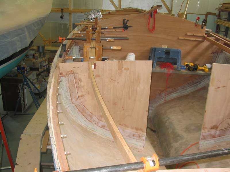
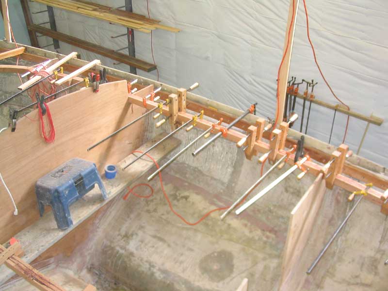
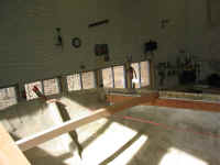
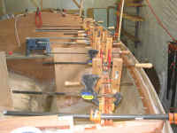
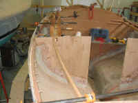 I dry fit the various carlin pieces on the
port side first, beginning at the forward end and working aft. I
staggered the joints between the various boards from layer to layer, and
after several hours' work I had the whole assembly dry-fit and clamped in
place so that I could eye it critically to ensure that the curve was sweet
and fair in all areas. As I had suspected, bending the three
thicknesses together through the various fixed points (as described on the
previous page) created a natural--and
pleasing--curve that was just what I wanted. I dry fit the various carlin pieces on the
port side first, beginning at the forward end and working aft. I
staggered the joints between the various boards from layer to layer, and
after several hours' work I had the whole assembly dry-fit and clamped in
place so that I could eye it critically to ensure that the curve was sweet
and fair in all areas. As I had suspected, bending the three
thicknesses together through the various fixed points (as described on the
previous page) created a natural--and
pleasing--curve that was just what I wanted.
|
|
 With the pieces on the first side dry-fit, the
next step was to glue up the pieces and clamp the whole assembly. I
unclamped the pieces and cleaned them all with acetone, then prepared for
the large-scale gluing by getting all my clamps organized up on the boat,
and preparing whatever other materials I might need. To glue the
pieces, I chose resorcinol glue, since it is much more user-friendly with
its long pot life and open working time. Epoxy simply doesn't work
in this sort of situation when working alone. I weighed out the two
components of the glue, and mixed it up. With the pieces on the first side dry-fit, the
next step was to glue up the pieces and clamp the whole assembly. I
unclamped the pieces and cleaned them all with acetone, then prepared for
the large-scale gluing by getting all my clamps organized up on the boat,
and preparing whatever other materials I might need. To glue the
pieces, I chose resorcinol glue, since it is much more user-friendly with
its long pot life and open working time. Epoxy simply doesn't work
in this sort of situation when working alone. I weighed out the two
components of the glue, and mixed it up.
|
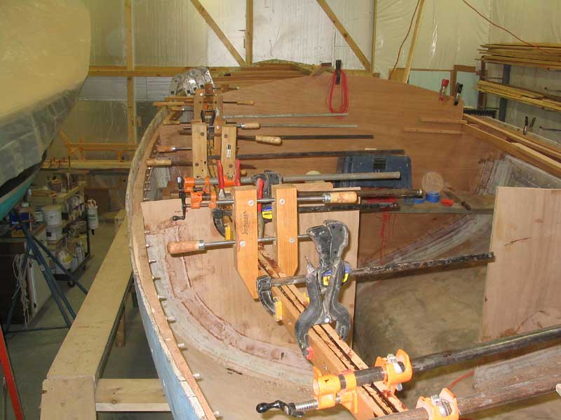
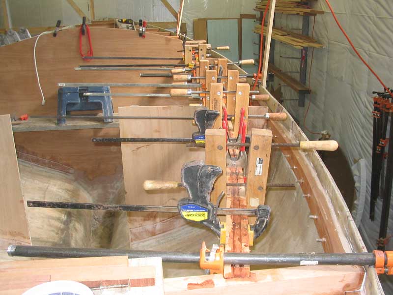
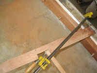
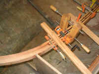
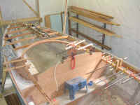
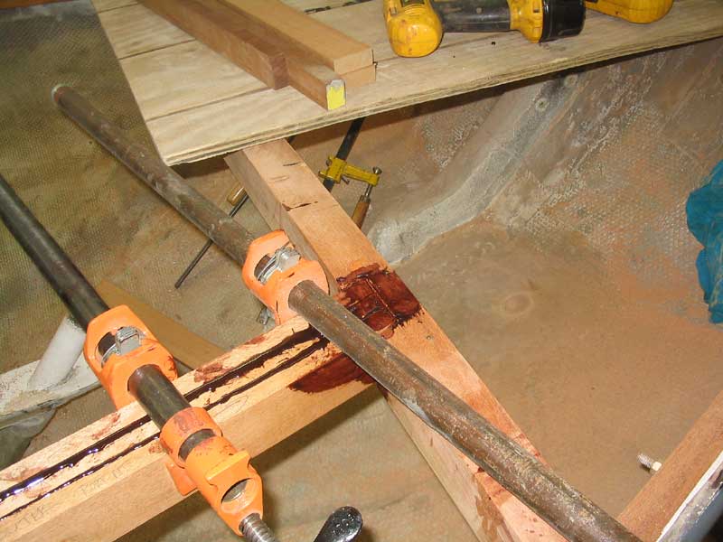
 Then I got right to work
spreading the glue on the pieces, working quickly but not rushed (at least
not too much). One by one, I got the surfaces coated and the pieces
installed, and then clamped everything up. Once I had all the boards
clamped tightly together, I eyed the new carlin from all angles to ensure
that the curve was still fair and what I wanted. In areas where the
carlins would not show in the finished boat (i.e. aft of the midships
bulkhead--the forward sections may be visible inside the boat), I used
some long drywall screws through the pieces to help draw everything
together; I'll remove these screws later, once the glue is fully
cured. I left the assembly to cure overnight, with the heat in the
shop cranked up to 70 degrees. Then I got right to work
spreading the glue on the pieces, working quickly but not rushed (at least
not too much). One by one, I got the surfaces coated and the pieces
installed, and then clamped everything up. Once I had all the boards
clamped tightly together, I eyed the new carlin from all angles to ensure
that the curve was still fair and what I wanted. In areas where the
carlins would not show in the finished boat (i.e. aft of the midships
bulkhead--the forward sections may be visible inside the boat), I used
some long drywall screws through the pieces to help draw everything
together; I'll remove these screws later, once the glue is fully
cured. I left the assembly to cure overnight, with the heat in the
shop cranked up to 70 degrees. |
|

|
|
|
|
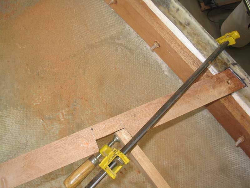
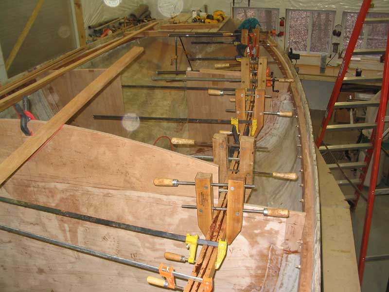
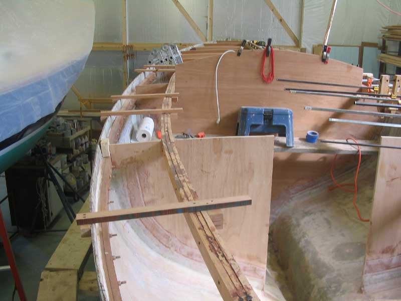
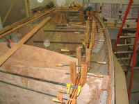
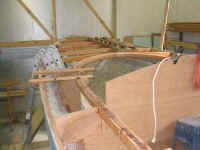
 The next morning, I installed some more
temporary wooden braces between the hull and the carlin to prevent any
movement of the carlin in relation to the hull during the next few
construction steps until the deck beams were permanently installed.
Then, I removed all the clamps, after determining that the glue was sufficiently
cured. I repeated the cutting, fitting, and gluing process on the
starboard side now, which was identical to the port side except that the
whole process went more quickly and smoothly than before. I compared
measurements from port to starboard so that I could ensure that both sides
were as close to identical as practicable. The next morning, I installed some more
temporary wooden braces between the hull and the carlin to prevent any
movement of the carlin in relation to the hull during the next few
construction steps until the deck beams were permanently installed.
Then, I removed all the clamps, after determining that the glue was sufficiently
cured. I repeated the cutting, fitting, and gluing process on the
starboard side now, which was identical to the port side except that the
whole process went more quickly and smoothly than before. I compared
measurements from port to starboard so that I could ensure that both sides
were as close to identical as practicable.
|
|
|
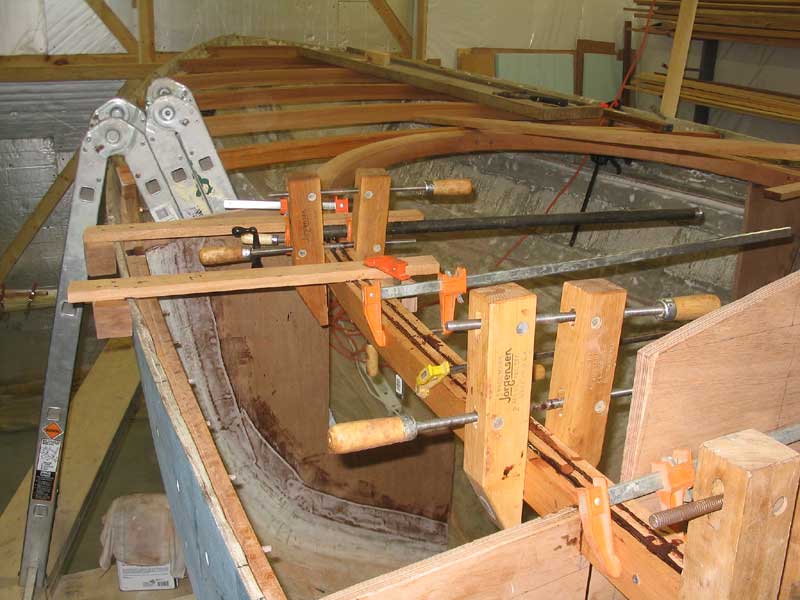
 Work
remaining on the carlins includes dressing off the tops to match the
designed deck camber, cleaning up any remaining glue squeezeout,
particularly on the bottom side, and some final attachment at the midships
and after bulkhead locations. Then, it's time to begin the process
if installing the short deck beams. Work
remaining on the carlins includes dressing off the tops to match the
designed deck camber, cleaning up any remaining glue squeezeout,
particularly on the bottom side, and some final attachment at the midships
and after bulkhead locations. Then, it's time to begin the process
if installing the short deck beams.
Continue> (coming
soon) |
|

|
|

 Then I got right to work
spreading the glue on the pieces, working quickly but not rushed (at least
not too much). One by one, I got the surfaces coated and the pieces
installed, and then clamped everything up. Once I had all the boards
clamped tightly together, I eyed the new carlin from all angles to ensure
that the curve was still fair and what I wanted. In areas where the
carlins would not show in the finished boat (i.e. aft of the midships
bulkhead--the forward sections may be visible inside the boat), I used
some long drywall screws through the pieces to help draw everything
together; I'll remove these screws later, once the glue is fully
cured. I left the assembly to cure overnight, with the heat in the
shop cranked up to 70 degrees.
Then I got right to work
spreading the glue on the pieces, working quickly but not rushed (at least
not too much). One by one, I got the surfaces coated and the pieces
installed, and then clamped everything up. Once I had all the boards
clamped tightly together, I eyed the new carlin from all angles to ensure
that the curve was still fair and what I wanted. In areas where the
carlins would not show in the finished boat (i.e. aft of the midships
bulkhead--the forward sections may be visible inside the boat), I used
some long drywall screws through the pieces to help draw everything
together; I'll remove these screws later, once the glue is fully
cured. I left the assembly to cure overnight, with the heat in the
shop cranked up to 70 degrees.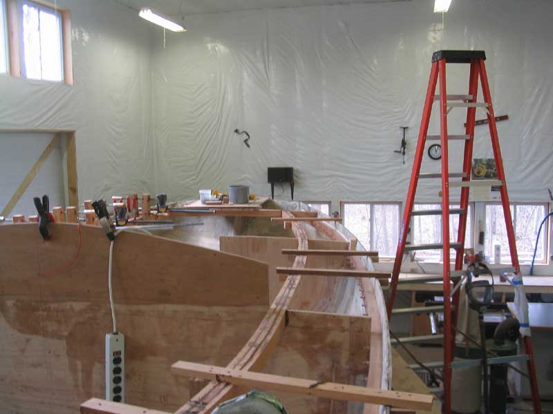 Work
remaining on the carlins includes dressing off the tops to match the
designed deck camber, cleaning up any remaining glue squeezeout,
particularly on the bottom side, and some final attachment at the midships
and after bulkhead locations. Then, it's time to begin the process
if installing the short deck beams.
Work
remaining on the carlins includes dressing off the tops to match the
designed deck camber, cleaning up any remaining glue squeezeout,
particularly on the bottom side, and some final attachment at the midships
and after bulkhead locations. Then, it's time to begin the process
if installing the short deck beams.