
110 Cookson Lane | Whitefield, ME 04353 | 207-232-7600 | tim@lackeysailing.com
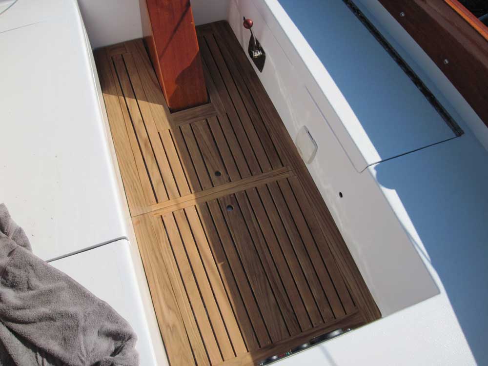
To complete the cockpit grating, all I needed to do was sand the new bungs smooth with the planks. This didn't take long, and afterwards I placed the grate in the boat.
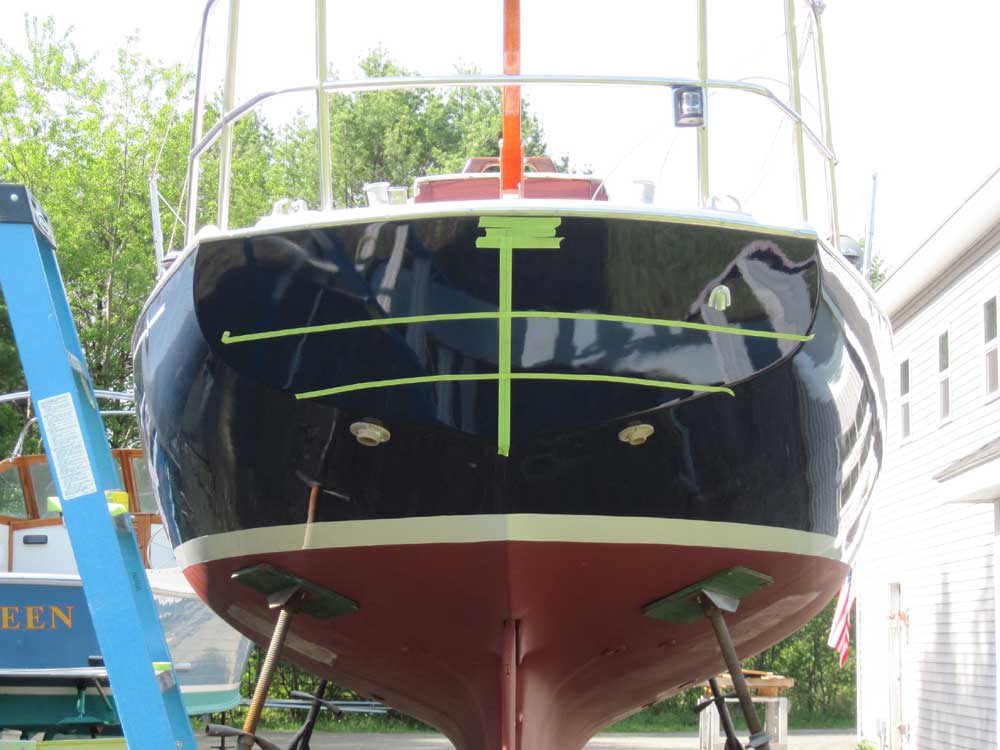
The owner decided to rename the boat, so yesterday I'd ordered the new vinyl graphics for the transom, and today I picked them up at the local vendor and prepared to install them. To begin, I worked out some layout on the transom. I wanted the name to follow the slight curve of the deck camber and the hailport to be straight and level, so I made various measurements and used tape to mark out centerline and baselines.
Note that this photo actually shows the lower tape line in the wrong spot: I'd originally curved it to match the upper line, but changed it to level afterwards.
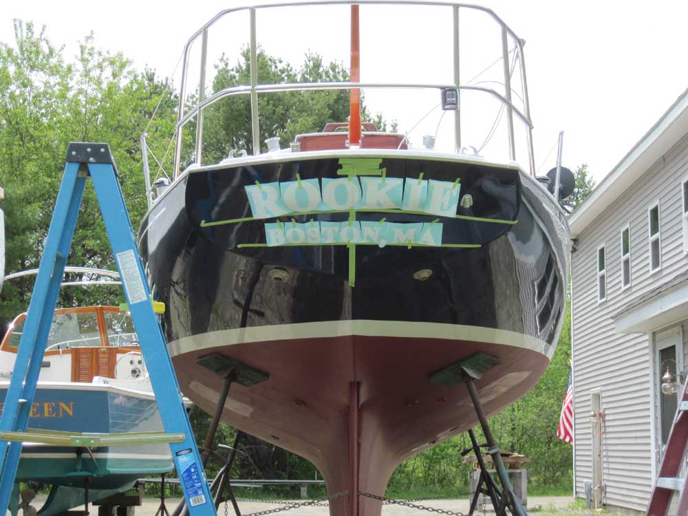
With the layout complete, I installed the final graphics. The letters, red with white outline, required a two-step installation, first the white portion, then the red. Because of the crown of the transom--that is, its fore and aft convex curvature--I had to align each letter individually to the baseline by splitting the vinyl mask between the letters.
I didn't like how the "K" turned out--it wasn't aligned properly with the letters on either side according to the slight curve of the baseline-- so I made plans to replace the "K" and align it properly.
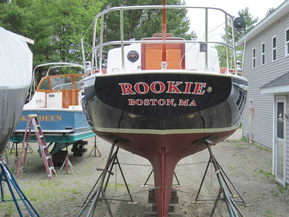
Fetching, laying out, and installing the letters took most of the morning and into the afternoon. A timely delivery of the anticipated electronics that the owner had ordered for the boat--VHF radio and GPS--meant that the remainder of the afternoon seemed the perfect time to take care of their installations.
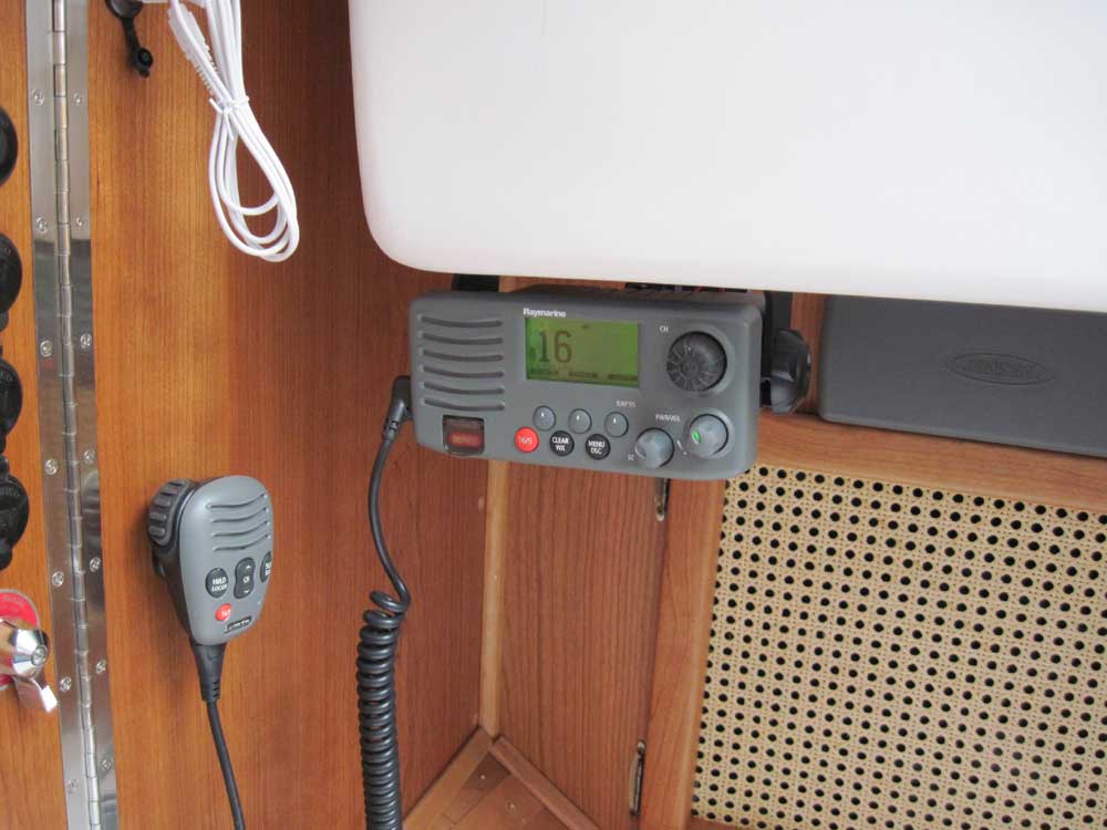
After considering a few locations, I decided the VHF would work best hanging from beneath the bridgedeck, adjacent to the electrical panel and clear of various door openings, yet easily accessible. This position also provided ready access to the stereo, located in the bulkhead behind, and was a simple location in terms of installation and wiring. I secured the bracket to the liner, then made up the wiring connections as necessary: power, antenna cable, and, according to the directions, a connection to the GPS's wiring harness NEMA +/- connectors to enable the DSC function on the VHF radio.
I powered up the unit to check its basic operation.
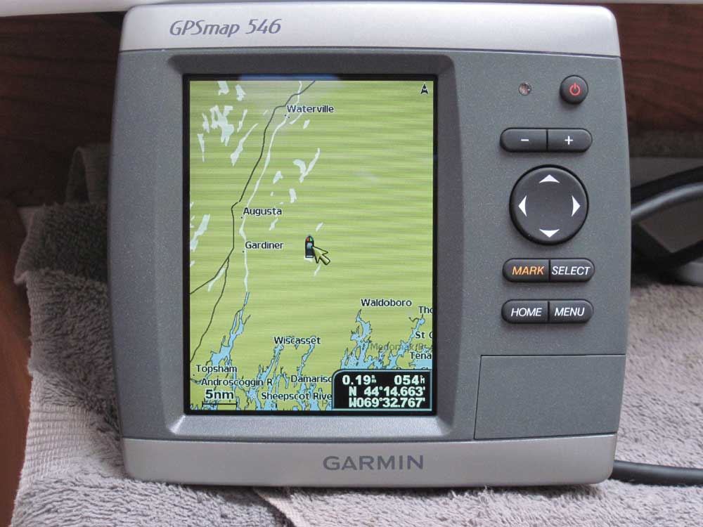
The GPS plotter would eventually mount to an aluminum swing-arm next to the companionway, so it could be used inside and outside the boat. I'd wanted to wait on the swing-arm order till the GPS was in hand, since I didn't know what kind of base would be required to mount the GPS bracket. So my first step was to determine this, and then order the appropriate swing-arm.
I also had to order an external antenna for the GPS, since they don't come standard.
Therefore, I couldn't complete the GPS installation, but did run the wiring harness and make the connections as required: power and NEMA +/- to the VHF, as mentioned above. Once the swing-arm arrived, I'd mount it and permanently install the GPS unit. I'd also install the external antenna as soon as it arrived.
However, with the power cable connected and the GPS's internal antenna, I could test its basic operation.
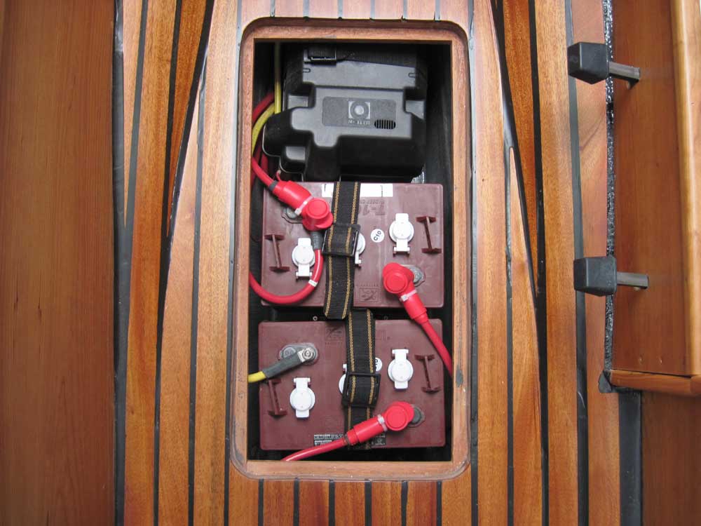
Finally, I installed some protective boots over the positive battery terminals, a small task I'd not completed earlier in their installation.
Total Time on This Job Today: 7 hours