| Circe
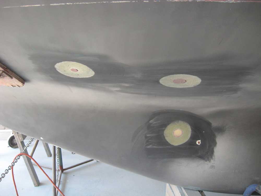
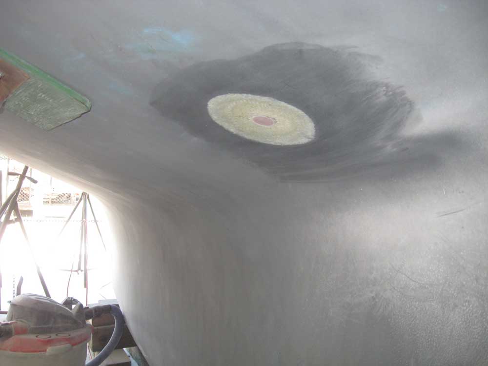
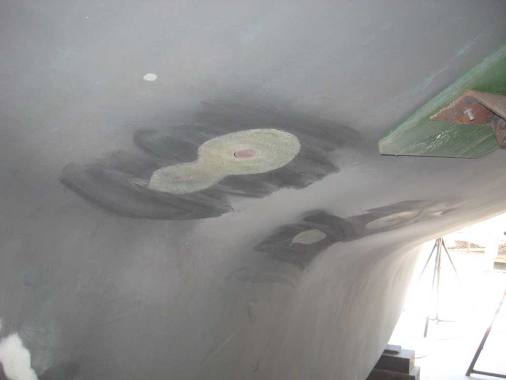
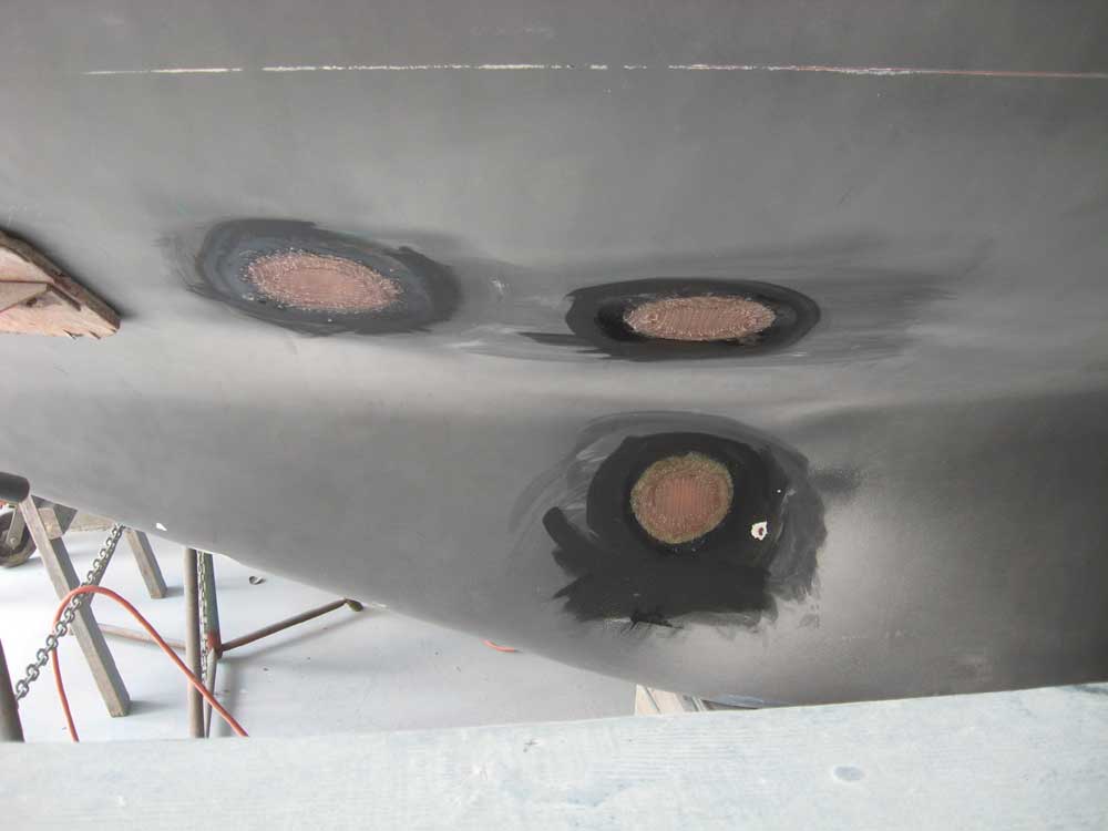
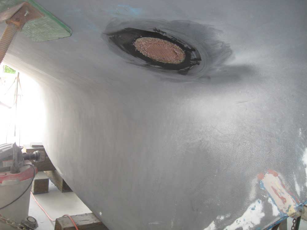
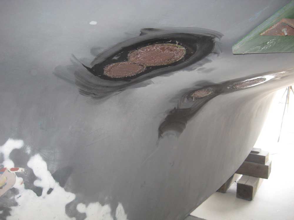
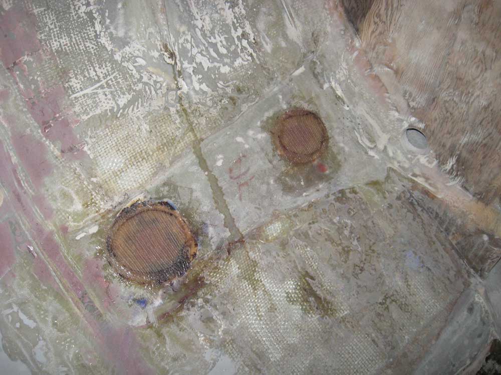
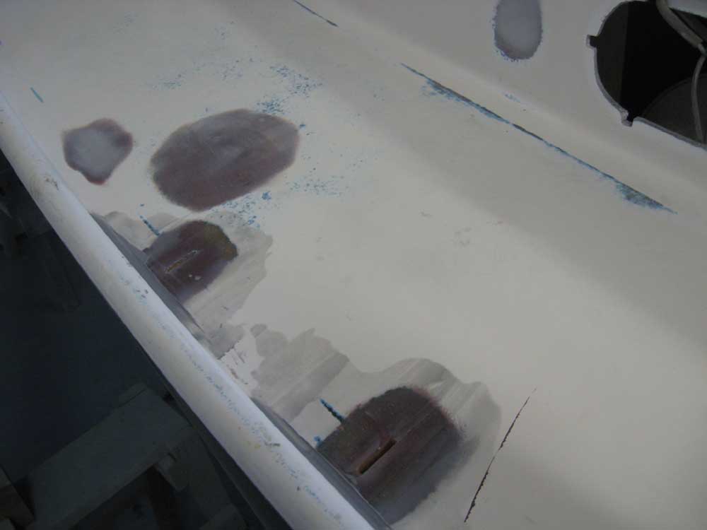
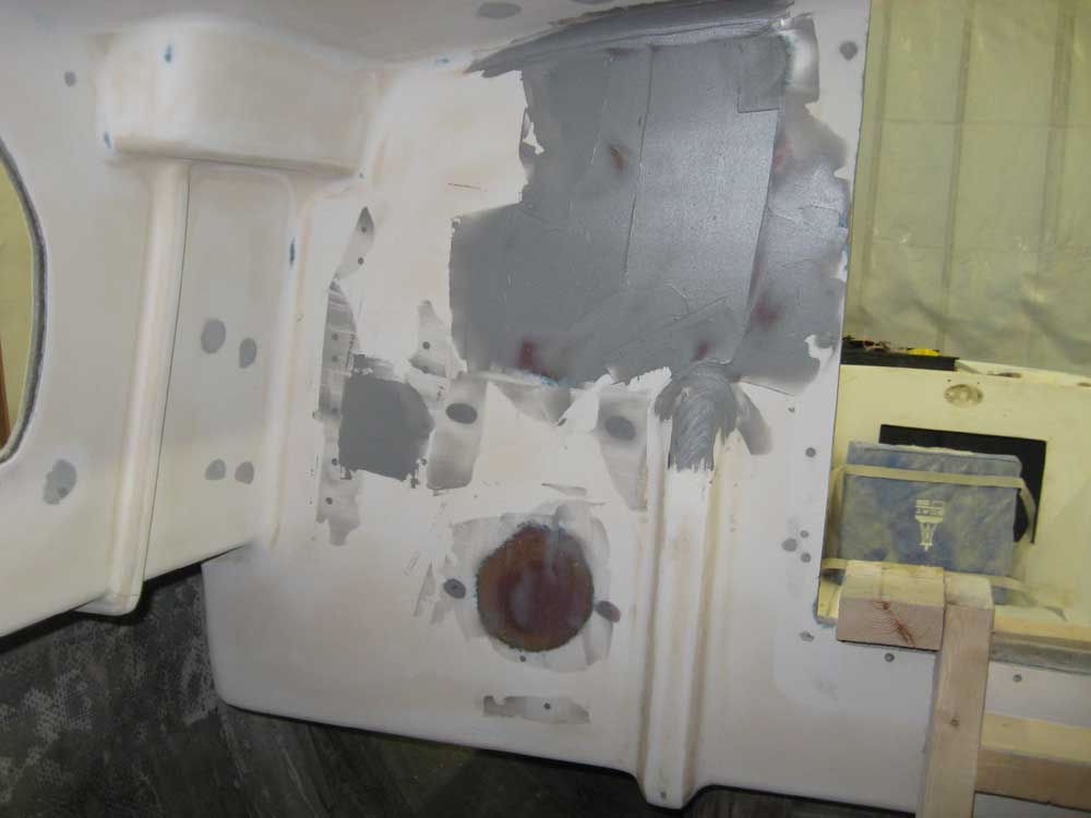
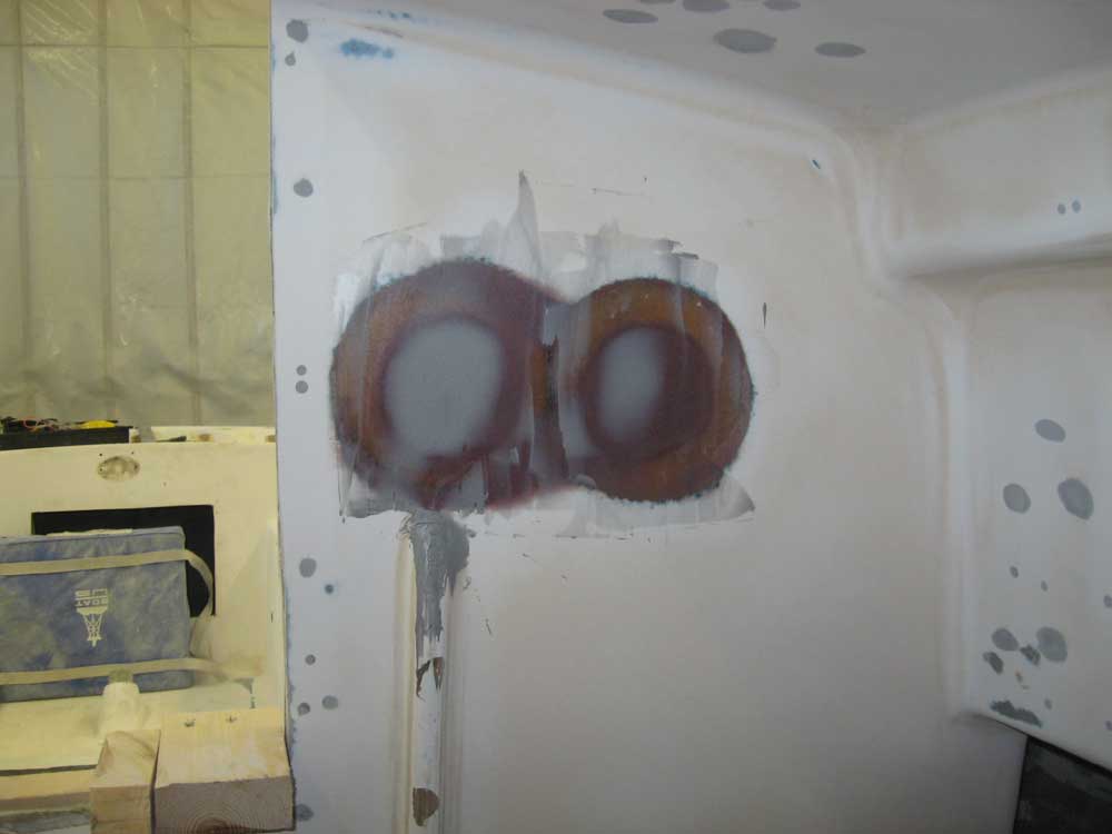
| Wednesday, August 19, 2009 Once again, I started my day at the controls of my various sanding machines. (It will end someday, faithful readers.) I sanded yesterday's application of filler as needed, both inside and outside, which mostly wrapped up the filling on the saloon liner--other than the patched instrument holes at the aft end, which would require additional work. Outside the boat, I removed the tape from over the outside of the through hull openings--now filled--and ground circular, dished areas around each hole to accommodate the exterior fiberglass patches. After cleaning up from this, I applied small amounts of filler as needed to take care of some minor voids in the epoxy plugs filling the old openings. Then, I installed pre-cut fiberglass rounds, laminated in epoxy, over each opening: 3 layers at each. Inside the boat, I applied two additional layers right over the now-filled holes. I patched all the through hulls to give me flexibility in locating any replacements without feeling bound to a pre-existing location that might not work ideally in the new arrangement. |
|
|
|
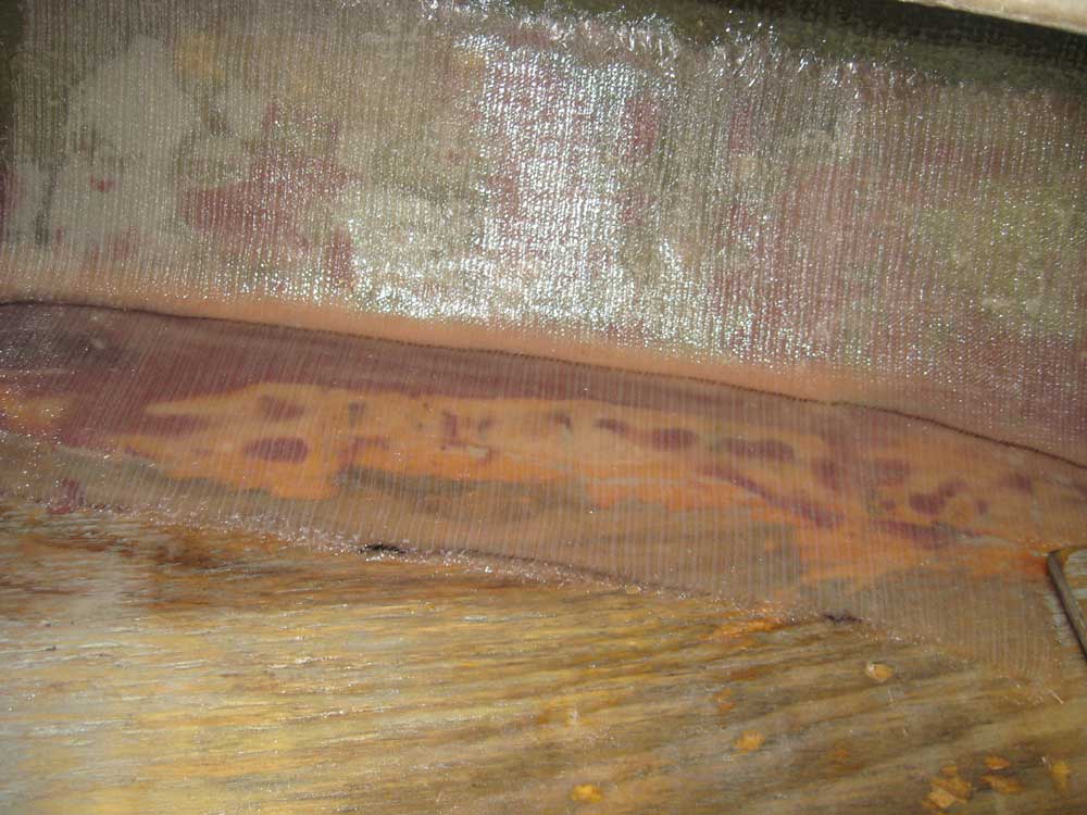
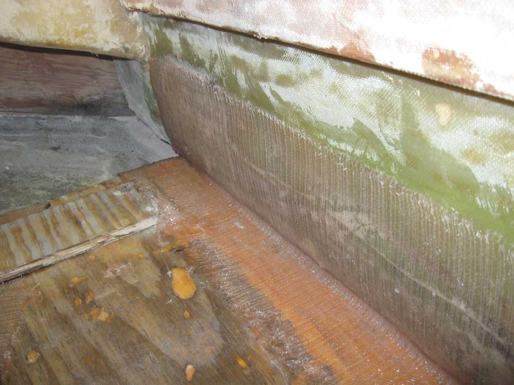
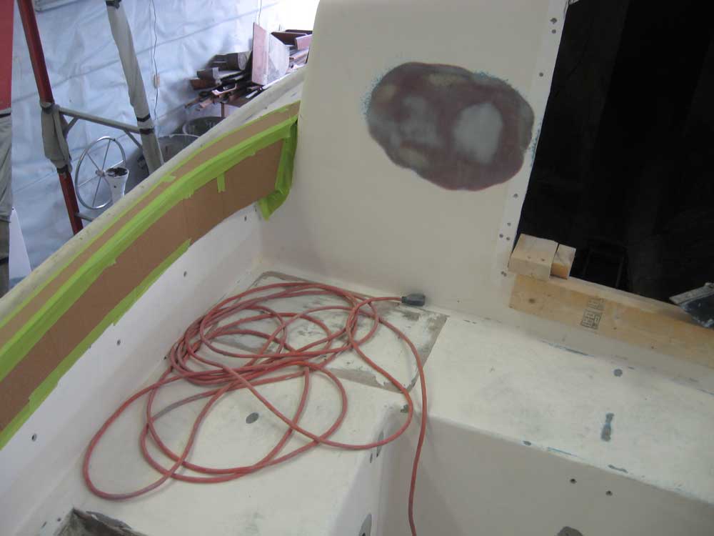
I cut a layer of custom tabbing to fit the fuel tank platform--both to tab it against the hull and also against the cockpit wall--and installed the new cloth with epoxy resin, reinforcing the pre-existing platform and overlapping the existing tabbing by a fair margin. Later, I planned to install a small bulkhead to further support the forward end of the platform. |
 |
|
Afterwards, I applied another layer of fine fairing compound to the interior instrument holes and around the newly-reworked chainplate slots, expecting this application to wrap up the work on the chainplates and possibly on the interior, though I'd not know for sure till the 'morrow. Because the starboard side of the saloon liner featured some distortion as produced by the factory, I applied the fairing compound here a bit heavier than I normally would, hoping to achieve some additional flexibility in creating a fair surface that melded with the natural contours of the liner as produced. |
 |
|
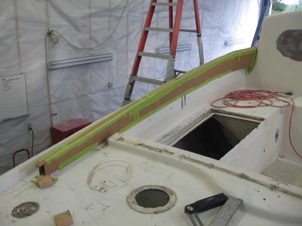
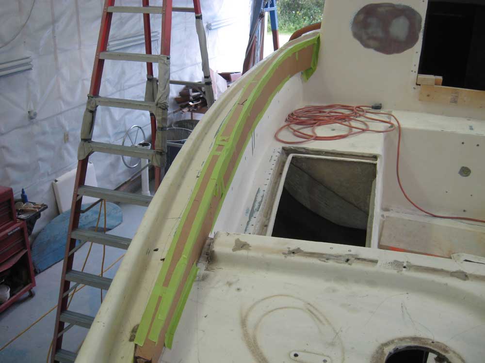
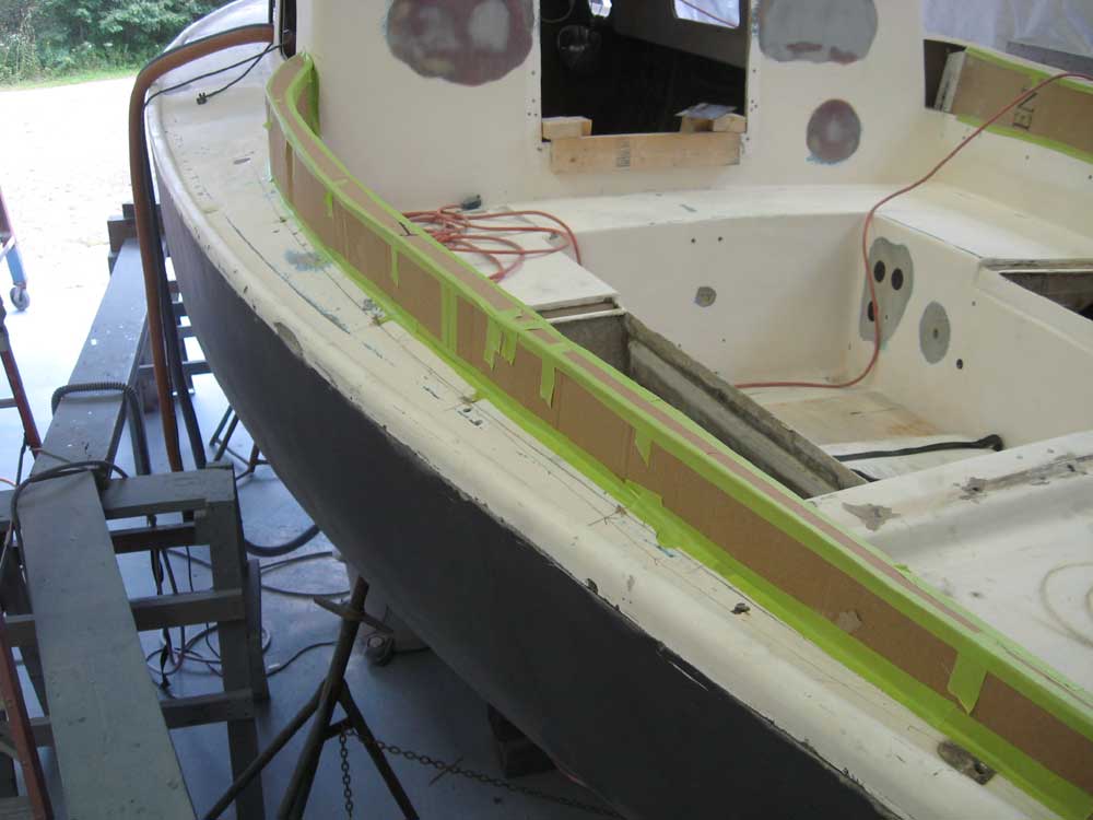
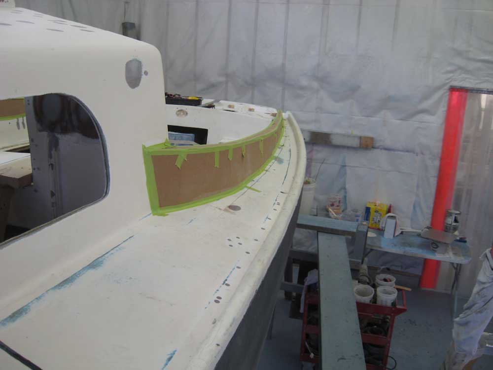
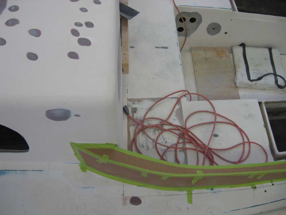
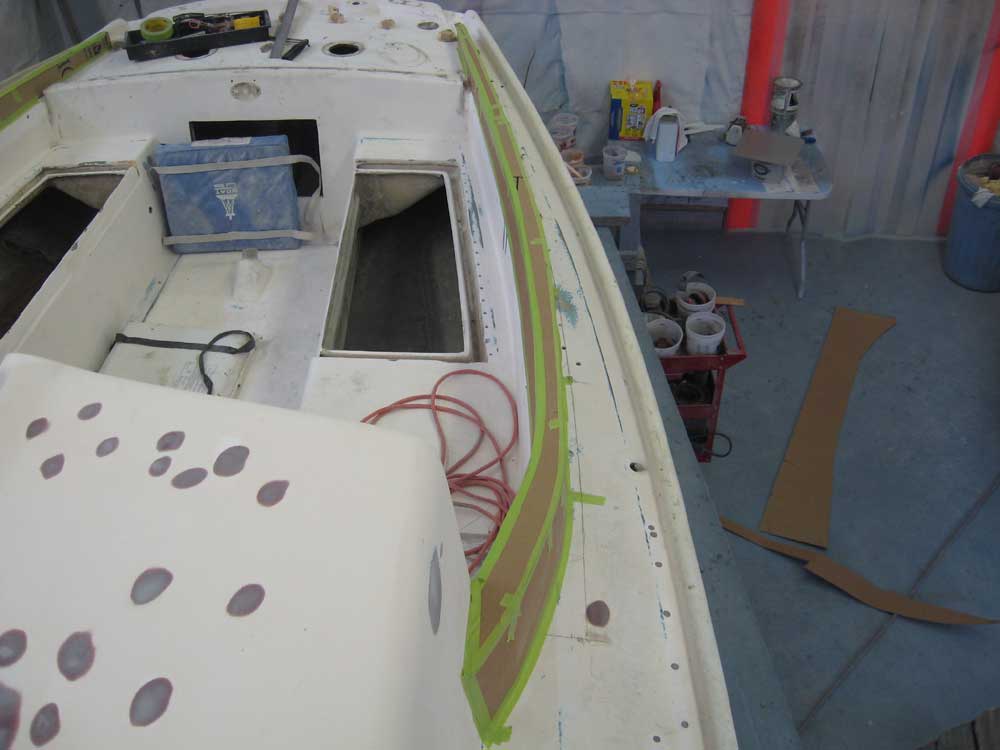
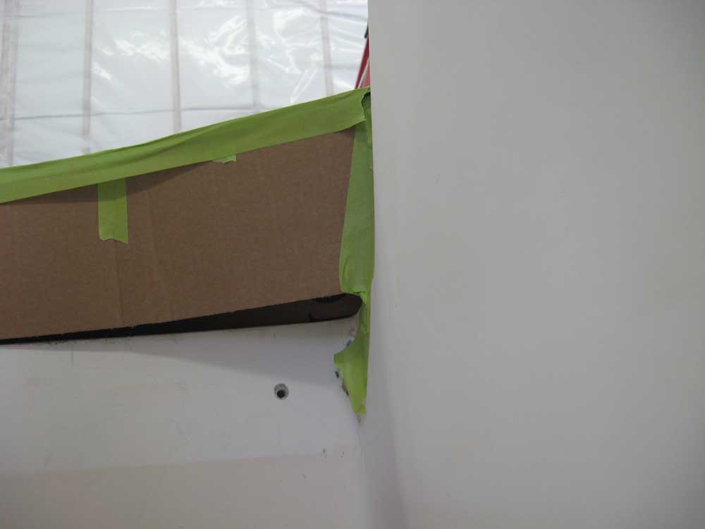
We'd had some discussion on the proposed cockpit coaming changes, and I'd spent a lot of time during the days quietly mulling over the possibilities and what might work to make the changes more effective and attractive. The design specification that had seemed the most restrictive, in terms of the efficacy of the aesthetics of the new coaming, was the desire for a "sit-able" width at the top of the coaming. This necessarily created substantial bulk to the coamings, particularly at the forward end, and my initial mockups--even the subtly altered starboard side--had not addressed this in as pleasing a way as I'd hoped, nor one that I was yet ready to accept. Conflicting schedules had meant that the owner hadn't been able to see the mockups in person, and this slowed down the further development of the plan of attack. Additionally, the owner thought that the aft coaming was too far aft, and needed to come forward some unspecified amount. I agreed; I'd originally set it up as far aft as it could realistically go, but there was no pressing reason it needed to be so far aft, which greatly limited the space available for hardware or other installations. The end result of all this was more questions and concerns with the coaming and cockpit design, and no clear solution immediately at hand, though the various ideas and modifications to the original design specification (most notably the concession that perhaps the coamings ought to be narrower than originally hoped) had given me additional information with which to work. So over a few days during which I had no time to address the coamings, I did spend plenty of time considering what might work. Narrowing the overall width of the coaming would substantially reduce its bulk, a worthy consideration, but the key to the overall appearance, I thought (beyond the basic contours and proportions of the coaming), was how to incorporate the forward end--the return. Because the molded cockpit area was several inches wider than the cabin trunk on each side, the coaming was necessarily already that far outboard of the cabin trunk, and providing a clean transition within these confines was proving to be the problem. Earlier, I'd had the idea of pulling the forward end of the coamings in, more in line with the cabin trunk. But my initial hopes had been dashed when, after looking at the boat, I thought that in order to do this and provide a fair, pleasing curve to the coamings, the coaming would end up stealing too much cockpit space, and the new line required for a fair curve might impact the existing cockpit locker openings--things we didn't want to do. Over time, though, I came to realize that pulling the forward ends in might be possible without such extensive modification, and without stealing too much valuable real estate--I just hadn't looked at it this way before, but I thought that the coaming could sweep cleanly into the cabin trunk beginning at the first "station" that I'd created during my initial coaming layout a couple weeks before. This would steal a bit of space from the forward corners, but would otherwise not impact the cockpit negatively--and the forward corners were dirt and water traps anyway. Only laying it out and building a mockup would tell me if the resulting curve would be appropriate. Therefore, I decided to remove the port coaming mockup--my first, and the one that I'd already deemed unsuccessful enough to make changes when I built the starboard side earlier--and try to bring my ideas to life. I began by reducing the width of the coaming: I decided upon a 1-1/2" width at the top, which, in the final version, might accept up to a 2" wooden caprail that could be OK for limited seating if desired. This would neither preclude nor confirm the possibility of a somewhat extended winch platform that might also accommodate seating, as suggested by the owner, but the eventual winch platform wasn't factoring into my concept at the moment--that would come later, once the basic coaming design was determined. Because of the taper required on the outside of the coaming, more or less to replicate that of the cabin trunk, the bottom edge of the coaming was somewhat wider. The forward end of this coaming design would also taper more widely as it went forward, because of the increasing height of the coaming and other factors; this feature didn't necessarily manifest itself in the rough cardboard mockup, but a final version of this coaming would end up being tapered not only in height, but also in width between the forward and after ends. Following the general construction techniques I used in earlier mockups, I installed vertical supports at the coaming "stations", this time ending at the one that was roughly 24" aft of the forward end of the cockpit. Then, I installed the "inside" of the coaming, and, from the first station, pulled this in to meet up cleanly with the aft corner of the cabin trunk. On the outside, I did the same thing, but brought the outer edge forward to its natural termination against the cabin trunk (roughly where the original coaming had ended, which was appropriate). As mentioned above, this created a slightly wider top surface as the coaming proceeded forward, which not only looked good and seemed natural, but also would provide more seating width than I'd originally thought. At the aft end, I left the coaming to run long, pending construction of a new after coaming in its new location (as of yet undetermined). I thought there was a lot of potential in this new design. It seemed to flow cleanly from the cabin trunk while staying relatively true to the original coamings' simplicity; the amount of overhang over the existing cockpit seat at the forward end was minimal, and I didn't see any worries about this, either in terms of construction complexity or stolen cockpit space. For some reason, I'd been slow to realize that the forward end of the coaming could work this way--between the earlier desire for a wider coaming, and my belief that the new coaming couldn't overlap the cockpit opening, it had taken me a while to realize that there was, after all, a way to make a different sort of transition at the forward end. I thought that if this concept in cardboard seemed successful enough, it'd be worth creating a more accurate mockup to ensure the contours of the proposal, and which would eventually be used as a real template for the final construction. As always, keep in mind that the cardboard (particularly the cardboard I seem to have on hand) simply cannot create as smooth curves as real material, so the mockup should be considered only as a general concept, not the final representation of the potential shape. |
 |
|
|
|