| Bolero
Project |
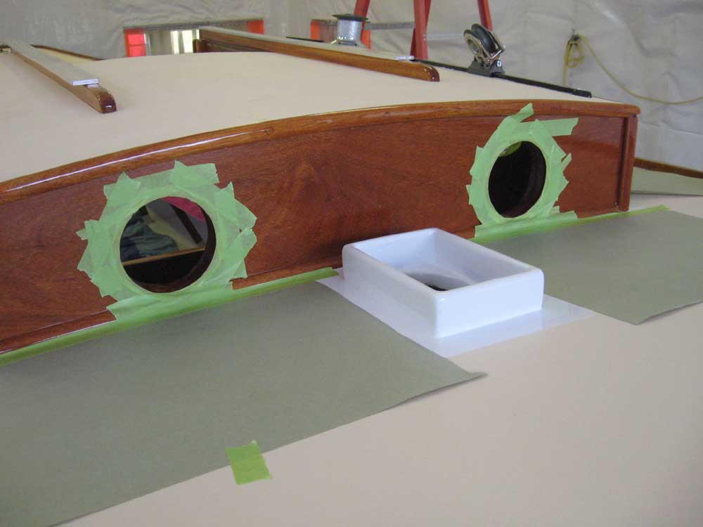
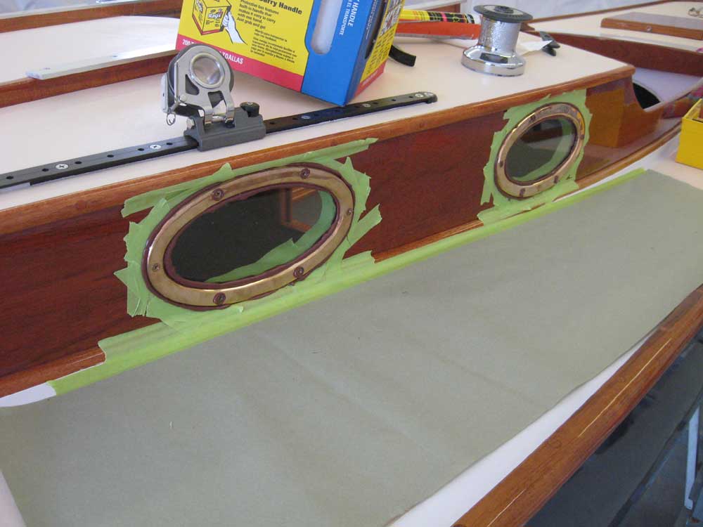
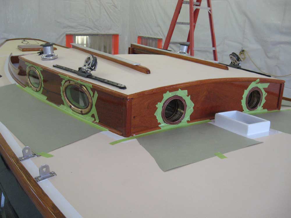
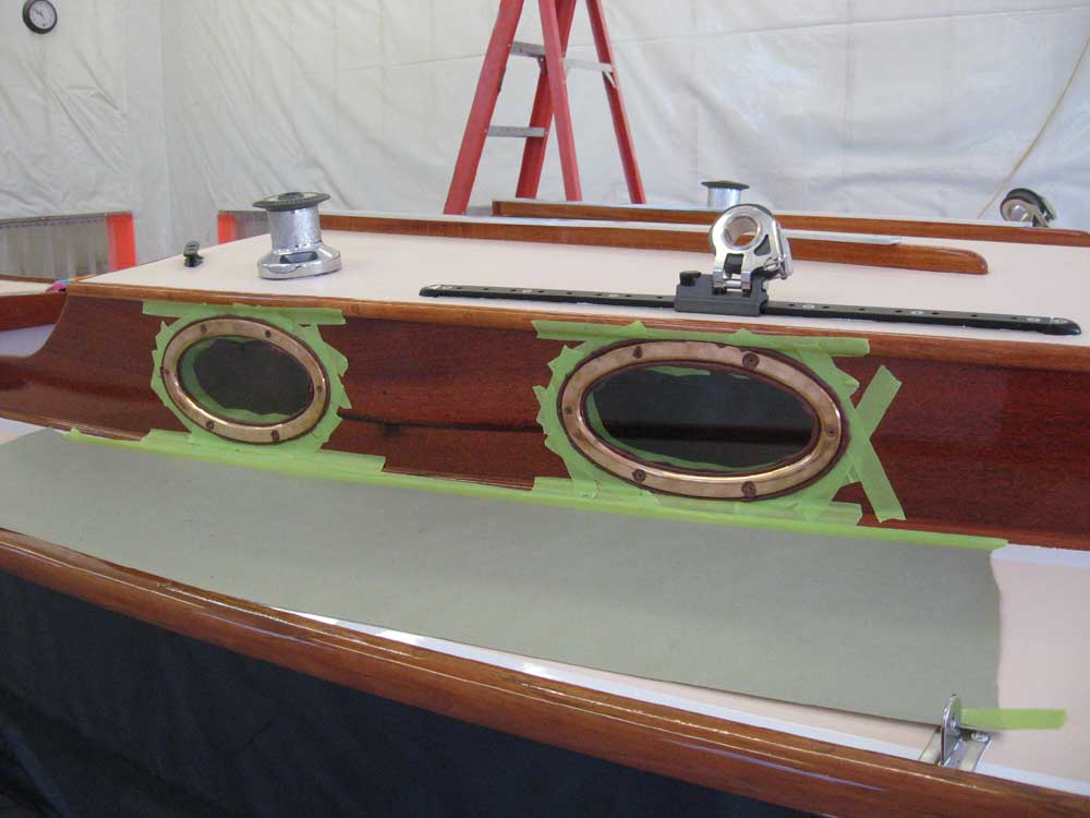
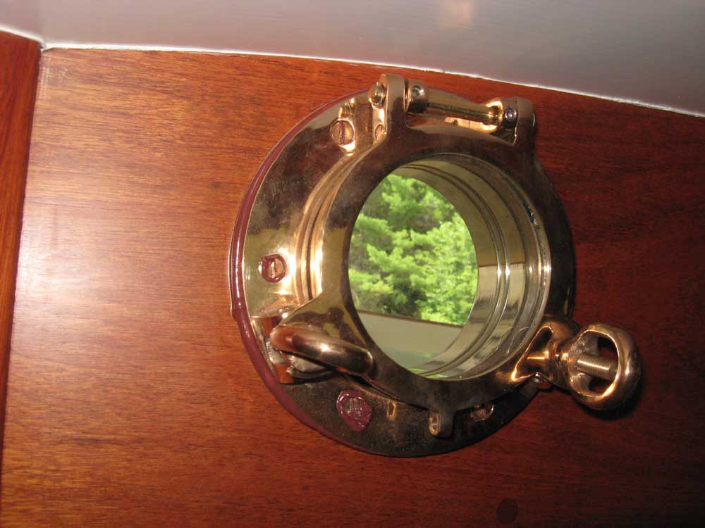
Sunday, July 27, 2008 While I hoped and expected to complete more, my main goal for the day was...wait for it... to install the ports. Yes indeed: the long vigil would soon come to an end. It had come to my attention recently that some people had become rather anxious to see the ports in place. I won't say who. In any event, I began by masking off the cabin trunk around the ports to avoid having the sealant squeezeout go everywhere, and avoid the need for excess cleaning with paint thinner on the new varnish. During much earlier steps in the construction process, I'd already labeled each port frame with its location and orientation, and pre-drilled the screw holes. |
|
|
|
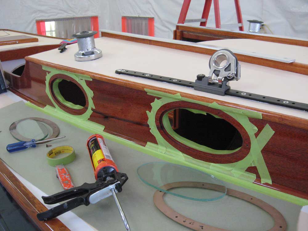
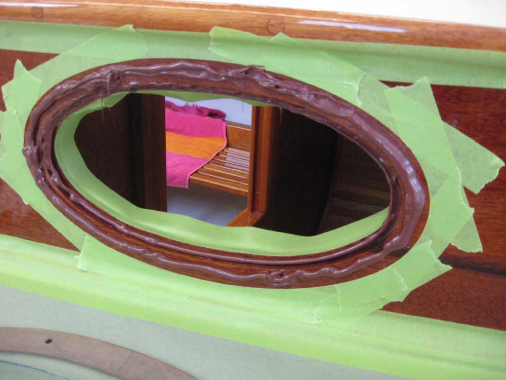
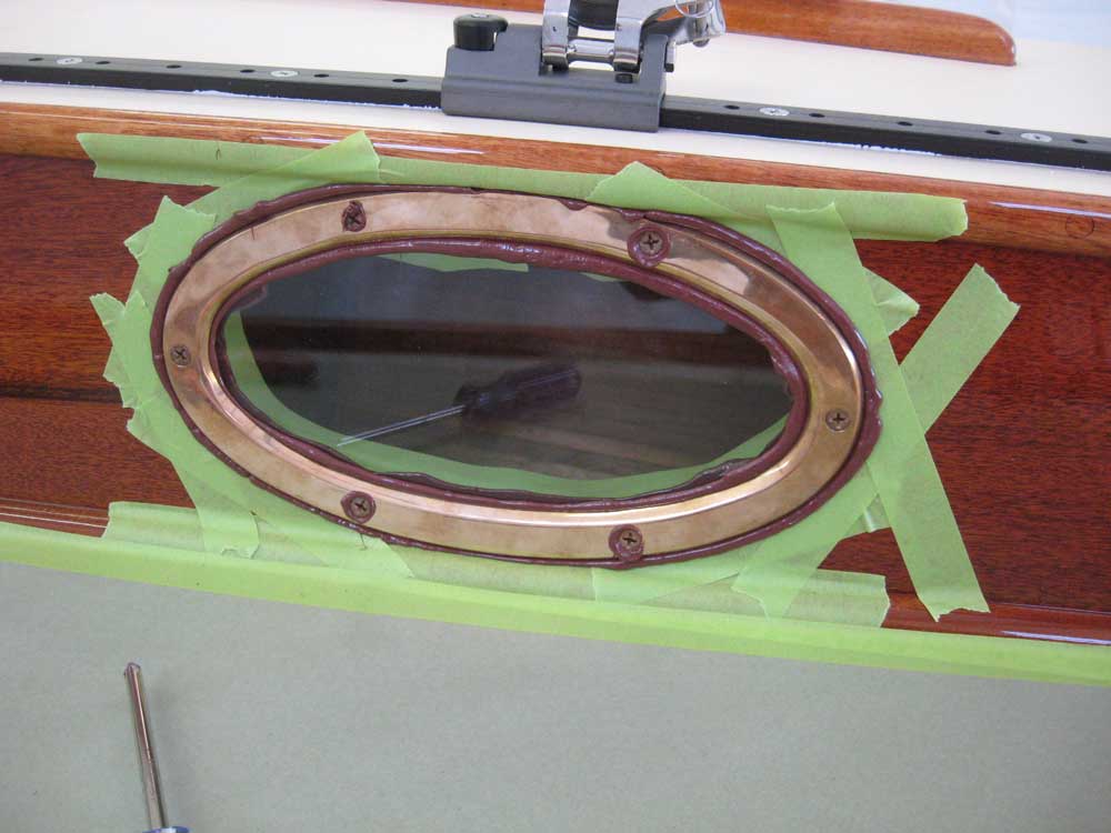
Final installation was quite straightforward. I used mahogany-colored polysulfide, and laid down a bead of the sealant in the rabbet beneath the glass, then inserted the laminated glass port. I installed additional sealant around the edges of the glass and on the cabin trunk itself, then screwed the bronze port frame in place with bronze screws. I left the sealant squeezeout alone to cure before I tried removing it, so, dear reader, you'll have to put up with one more day before you can see the ports without the tape and caulk all over the place. |
|
|
|
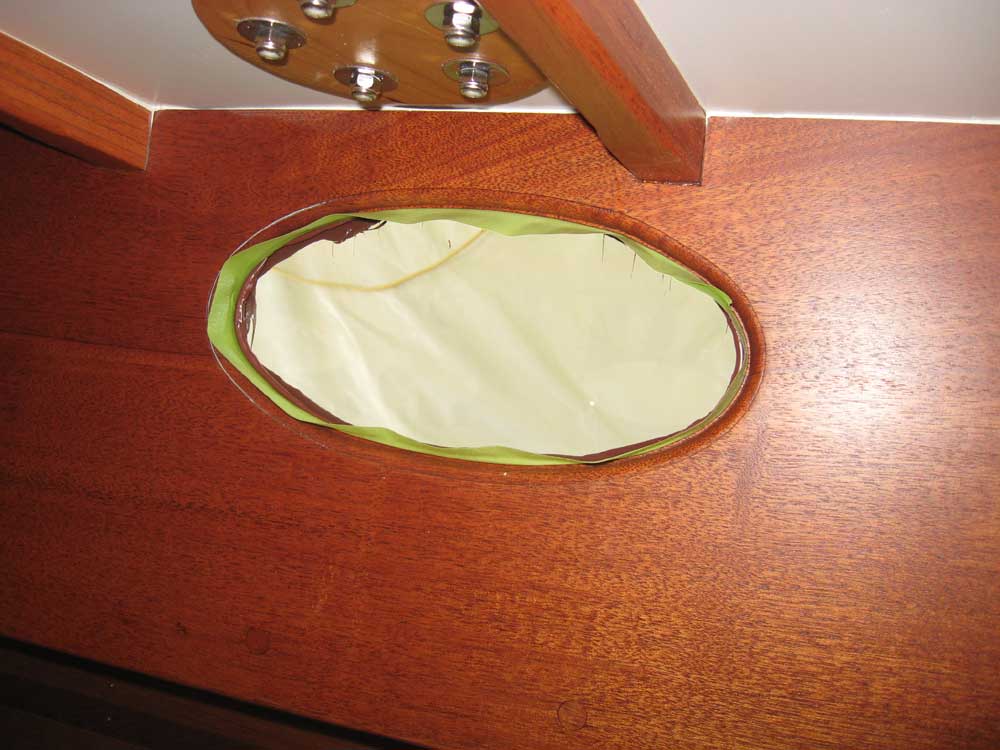
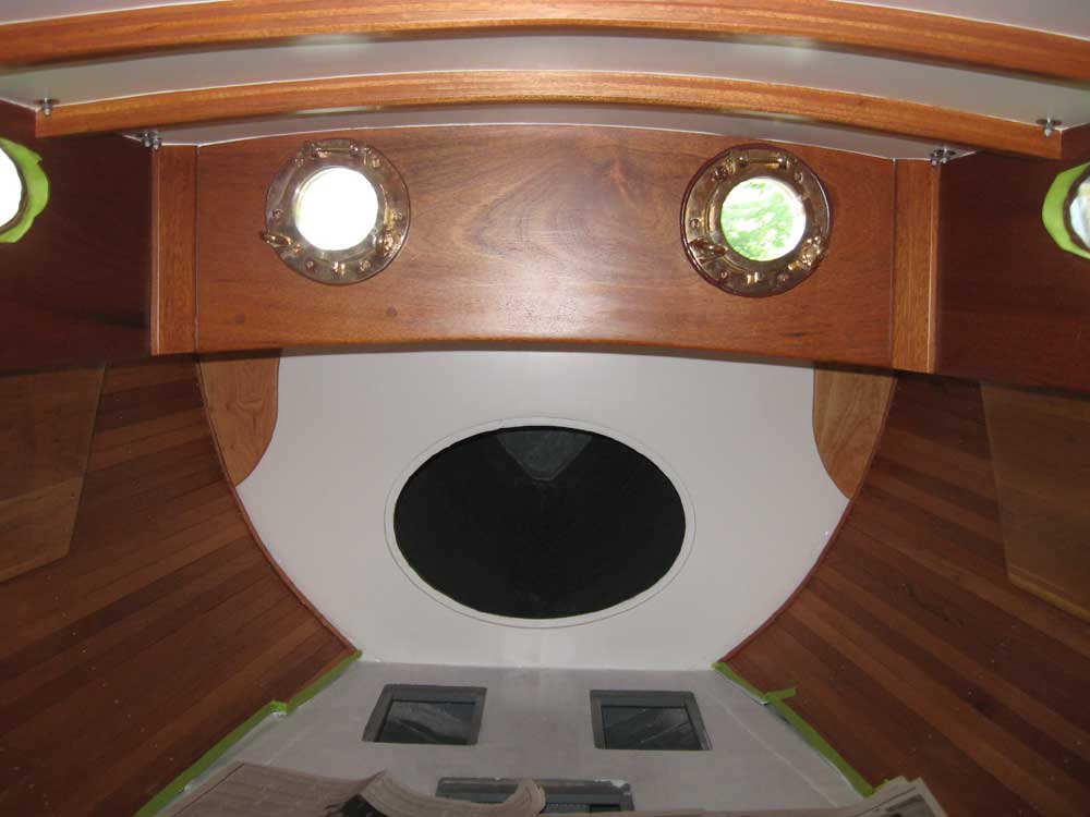
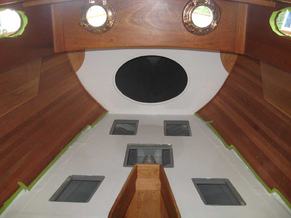
Similarly, I installed the two round forward-facing opening ports. I applied sealant to the inside of the mounting flange and onto the spigot a bit, then inserted the ports in their openings and screwed them in place. I used way too much sealant on the first (starboard) port, so reduced the amount on the port port. Then, from outside, I applied additional sealant around the slightly-protruding bit of the spigot and smoothed it out to seal the remaining opening as needed. |
|
|
|
Once I was sure no sealant was going to fall upon parts of the interior, I proceeded with the second coat of white paint on the v-berth platform. I also varnished the small parts that I had underway. |
|
|
|
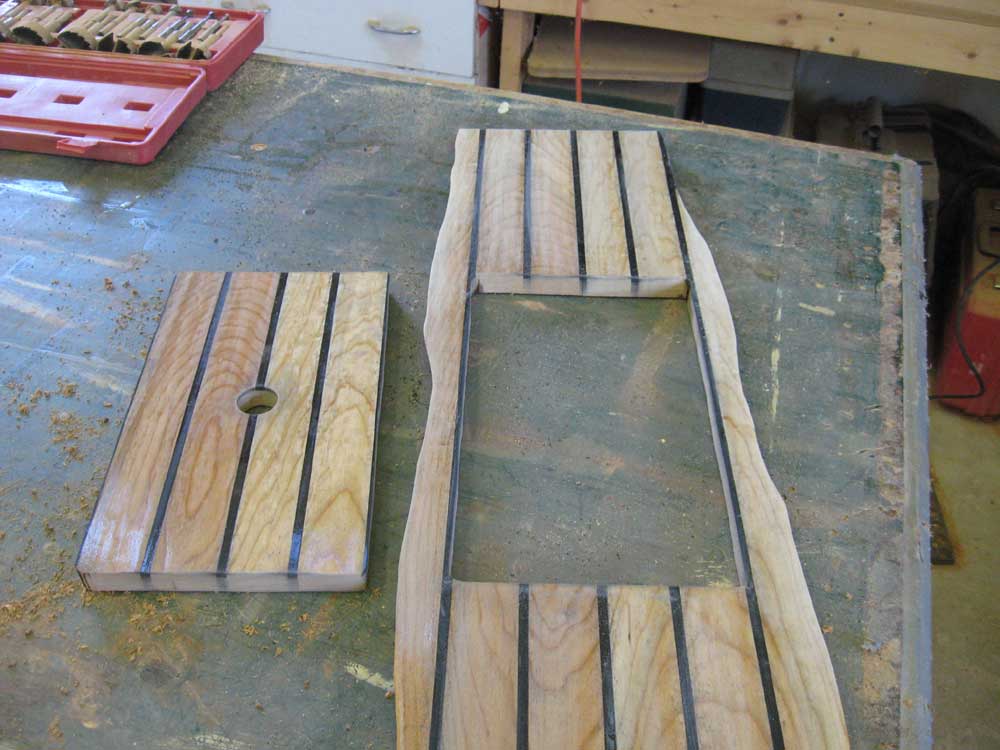
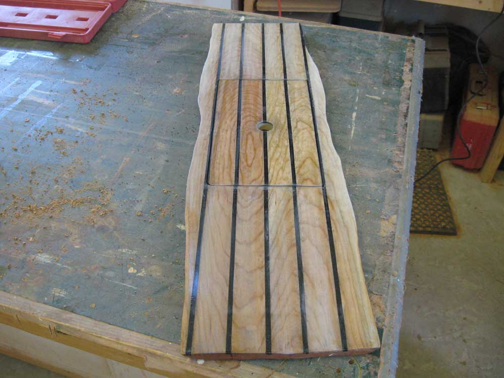
Before I continued with the cabin sole, I needed to cut an opening hatch in its center to provide basic "sponging" access to the bilge in the cabin; the entire sole would be removable without too much difficulty for access to the keelbolts in the future, but I didn't intend the sole to be completely removable on a regular basis. In the boat, I used tape to mark, on the hull, the locations of the sole supports in the bilge. Then, I wrapped some tape beneath the sole piece, leaving long edges that I could use to pull the sole back up out of the boat, and installed it temporarily so that I could mark the locations of the supports and ensure that the opening hatch ended up spanning between two of these supports. Finally, I cut the opening with a jigsaw, and cut an ample finger hole in the new hatch's center. |
|
|
|
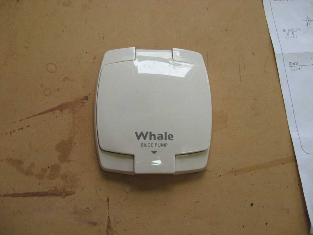
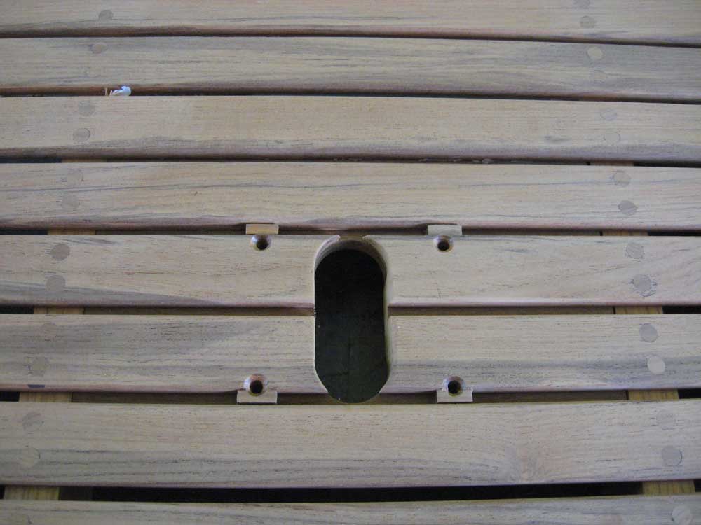
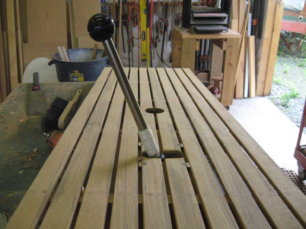
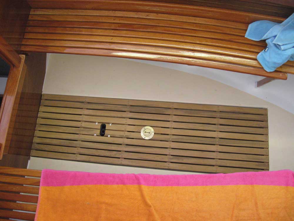
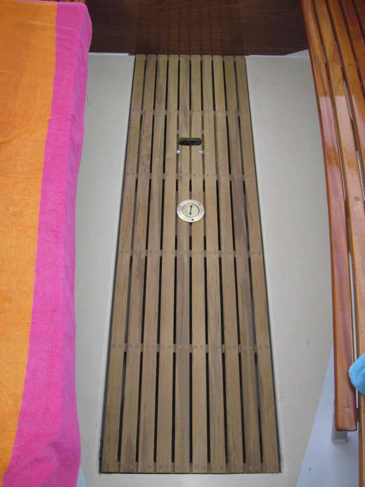
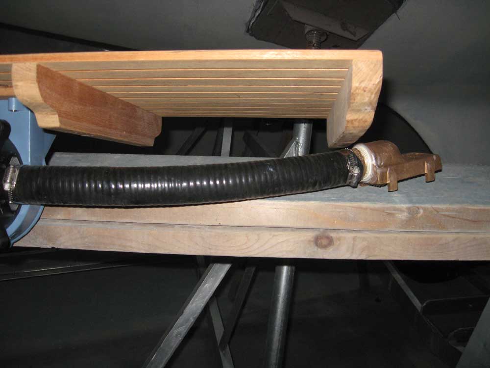
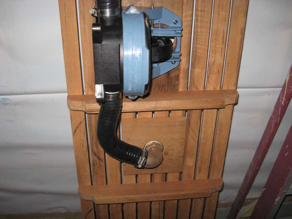
I turned my attention once more to the cockpit sole grate. The glue securing the bungs had cured, so I chiseled and sanded them smooth and level with the surrounding surface. Next, I continued with the bilge pump installation. The pump came equipped with a disgusting and weak plastic "through-bulkhead" cover plate designed to aid in installation and provide an ostensibly watertight seal to the pump mechanism when the pump was mounted through an otherwise watertight bulkhead. In this case, however, with the pump intended to go beneath the cabin sole, there was no way I was going to use the cheesy plastic arrangement, since I knew from seeing battered and broken ones on numerous boats over the years that it would break the first time someone stepped on it. Plus, it was ugly, and in this particular installation there was no need to provide any semblance of water resistance, since the sole itself was open to the weather and the bilge. |
|
|
|
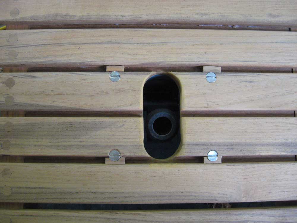
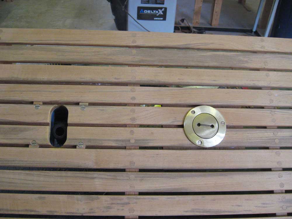
Instead, I cut a slot through the sole directly above where the pump handle socket would end up, and then installed the pump beneath. This provided the necessary access for the handle with minimal impact on the visual and functional aspects of the cockpit sole. I test-fit the completed sole in the boat with acceptable results. |
|
|
|
I continued by cutting an appropriately-sized hole in the next section for a bronze deck fill plate, which I installed along with a 90° tailpiece that I connected to the adjacent pump body with a short length of hose. Finally, I installed a second length of hose, equipped with a bronze strainer at its inlet, for the pump's intake line. For the pump's ultimate discharge line--that which would screw into the deck fitting and pass over the side when needed--I supplied a 10' length of hose with the appropriate threaded fitting at the end. |
|
|
|
|
|