
110 Cookson Lane | Whitefield, ME 04353 | 207-232-7600 | tim@lackeysailing.com
Blue Teal | Tuesday, July 2, 2013
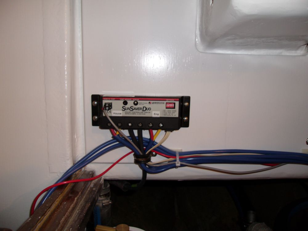
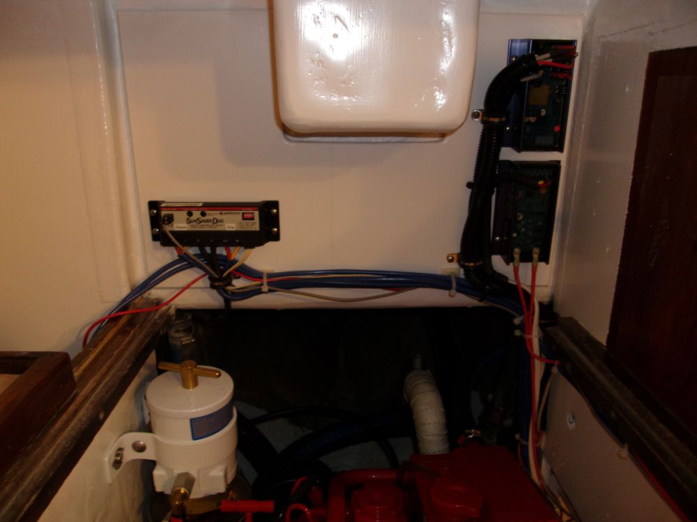
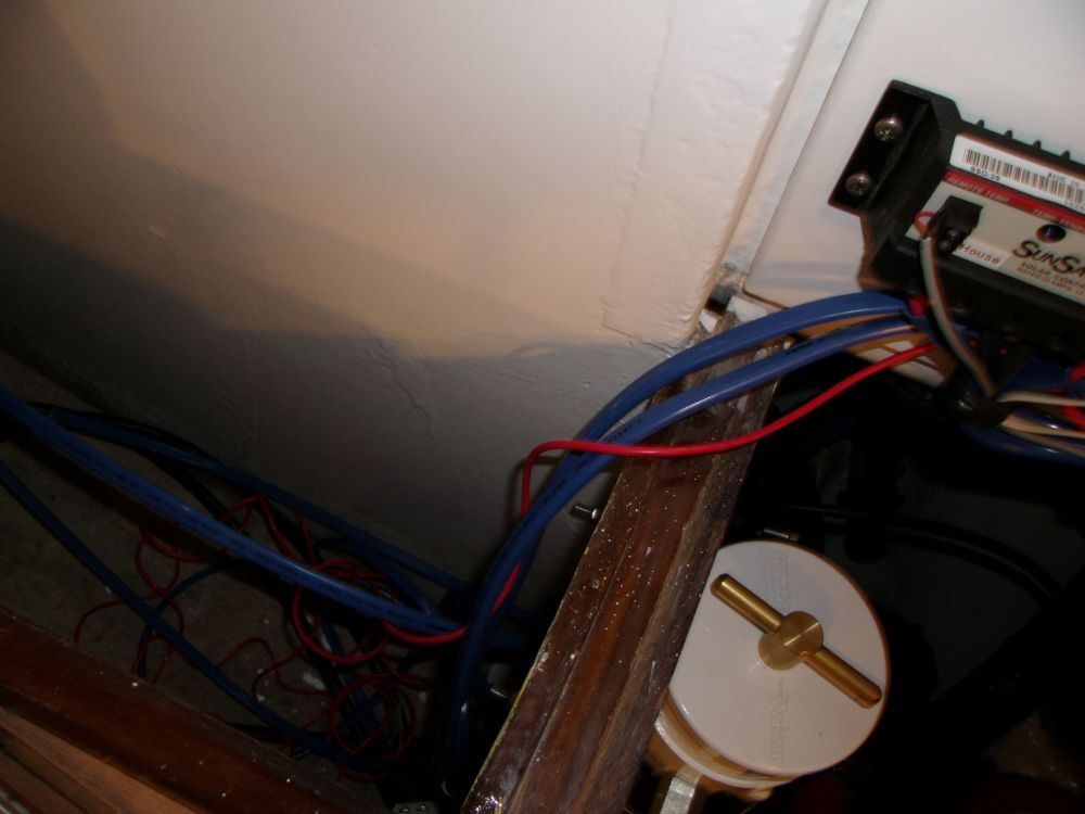
I spent the day on various wiring tasks, concentrating on the engine room and the port side of the boat. During the day, I made the final connections to the solar controller, including the input from the solar panel, outputs to both battery banks (for later connection once the batteries were in place), a temperature sensor, and network cable to connect the controller with a remote display to be located near the electrical panel.
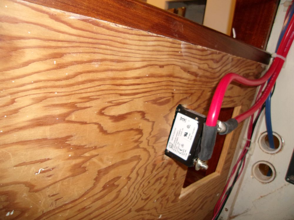
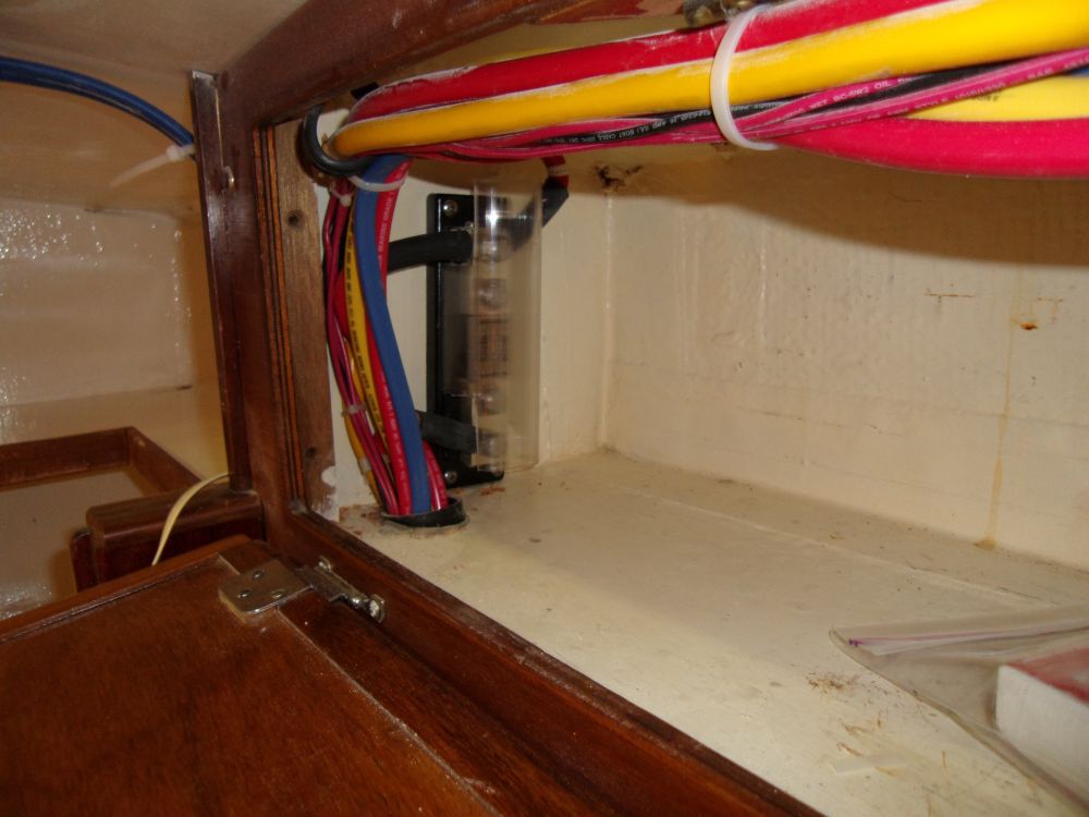
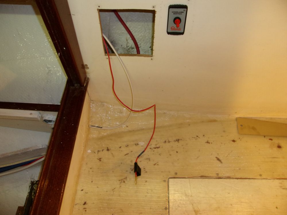
I made up the final connections to the windlass main breaker using the cable runs I'd installed earlier, and connecting the negative lead and main power to nearby buss bars.
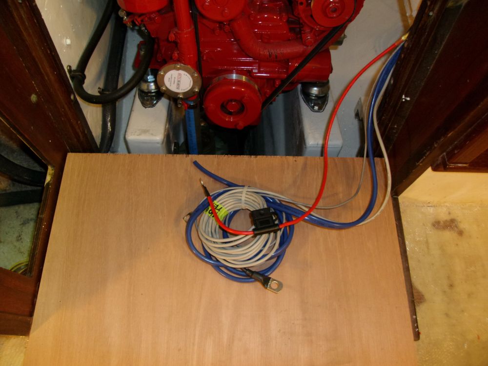
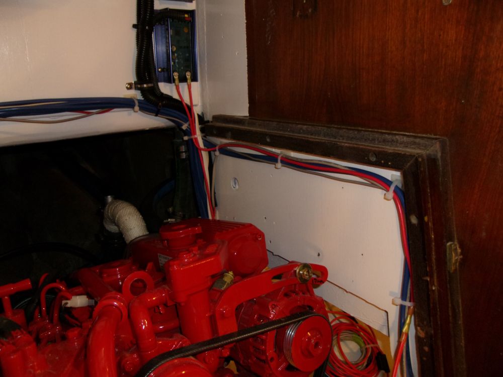
I made up the remaining connections required for the alternator regulator and Duo-Charge start battery charging system, including the input and output wires. Correspondence with Balmar tech support indicated that extending the short 24" stock input lead by a couple feet as we needed to do would pose no problems, so I extended this cable as necessary to reach the house battery bank forward of the engine.
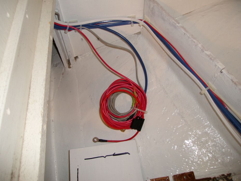
Other new connections to these two devices included battery temperature sensors from each battery bank to the regulator, negative connection to the Duo Charge, and power wires from the regulator harness to the ignition switch for the engine (raw wire only; to be connected later), plus a power lead from the Duo Charge to the start battery switch location (raw wire only; to be connected later). Note that the Duo Charge output wire leading to the start battery was intentionally left over eight feet in length despite the battery's proximity to the engine, as this is how it was directed to be. I bundled the various wires that would later be connected to each battery bank.
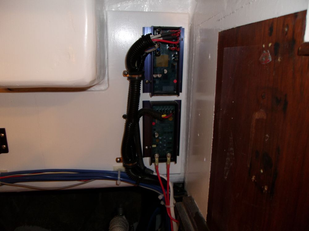
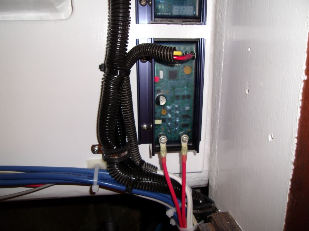
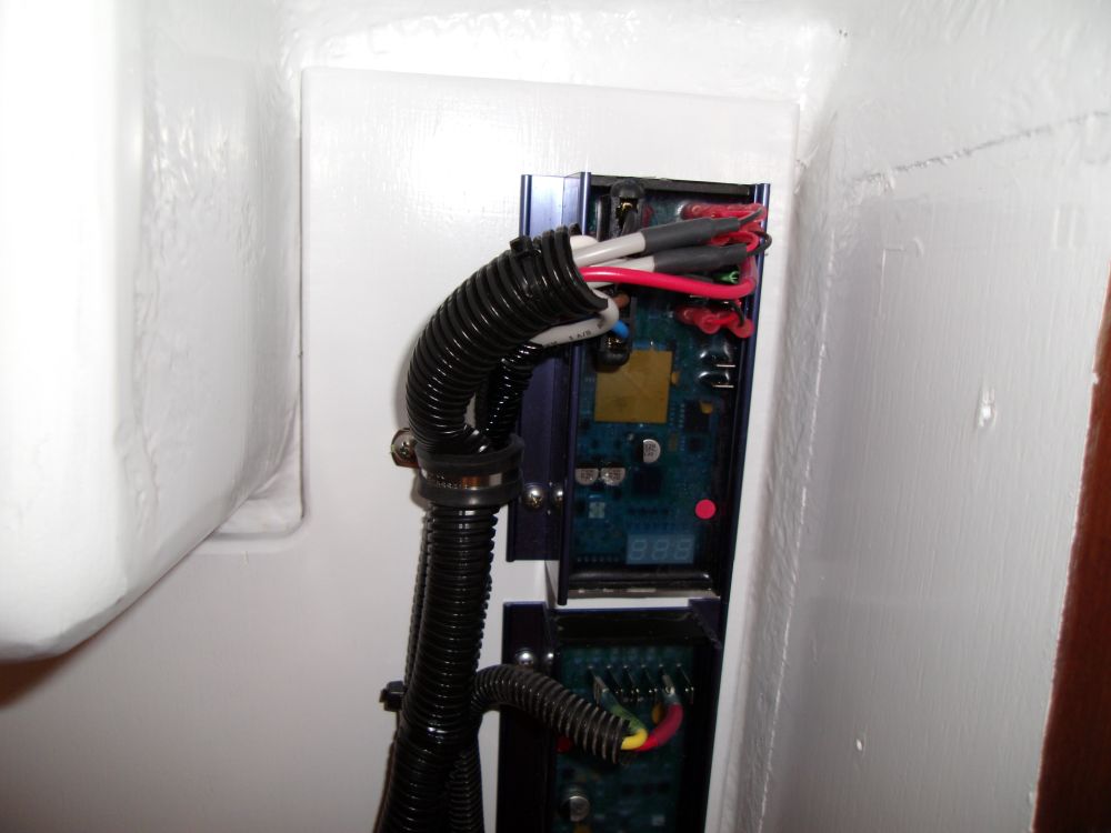
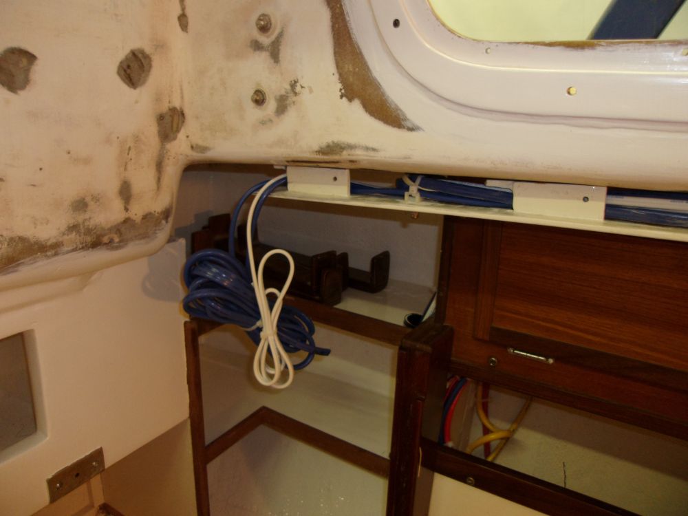
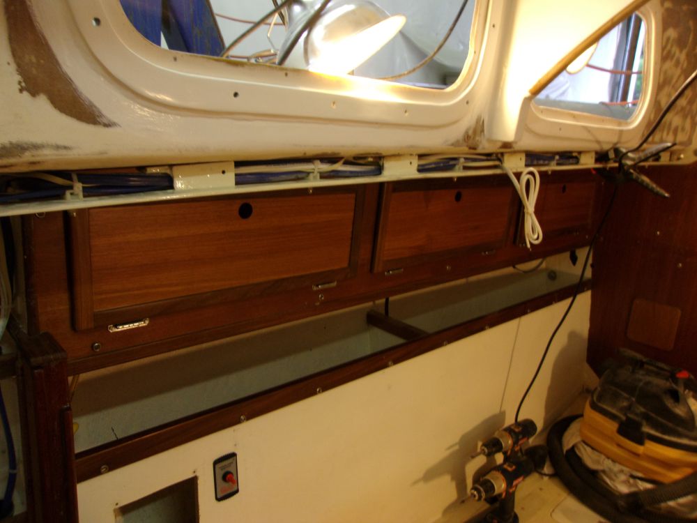
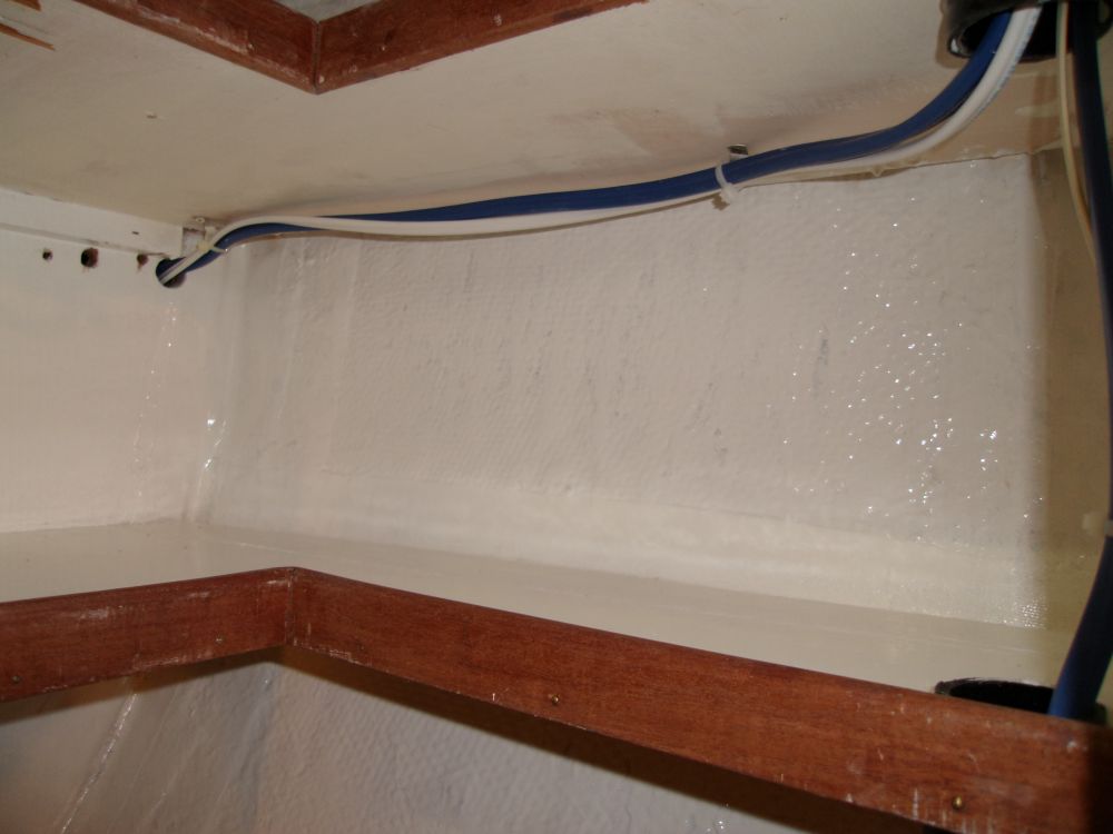
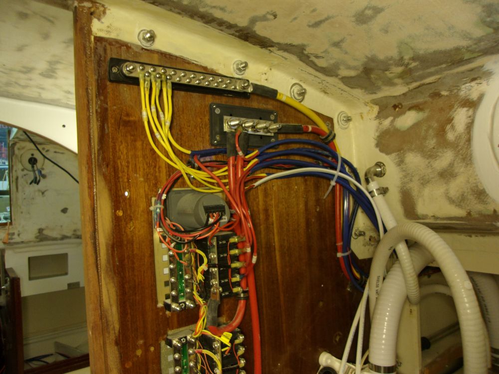
Along a port-side wiring chase installed previously by the owner, I ran leads for interior lighting, stern light, autopilot, and navigation and 12-volt circuits to be led beneath the dodger for various and later use. In the head, on the business side of the electrical panels, I made up whatever connections I could for the moment, leaving the cable runs unsecured for now pending additional wire runs in the coming days, and secured the wire runs along the port side, leaving a few raw circuit ends dangling for later routing and connection to interior lights (white-sheathed conductors at the aft end and center) and the port dodger power supplies (blue-sheathed conductors at the aft end).
Meanwhile, I dead-ended several cables and wires that would eventually lead up the starboard aft bulkhead and to the engine panel and/or electronics mount and dodger area (for additional electronics or accessories); I'd complete these wire runs once the final coverings for this and other surfaces were complete.
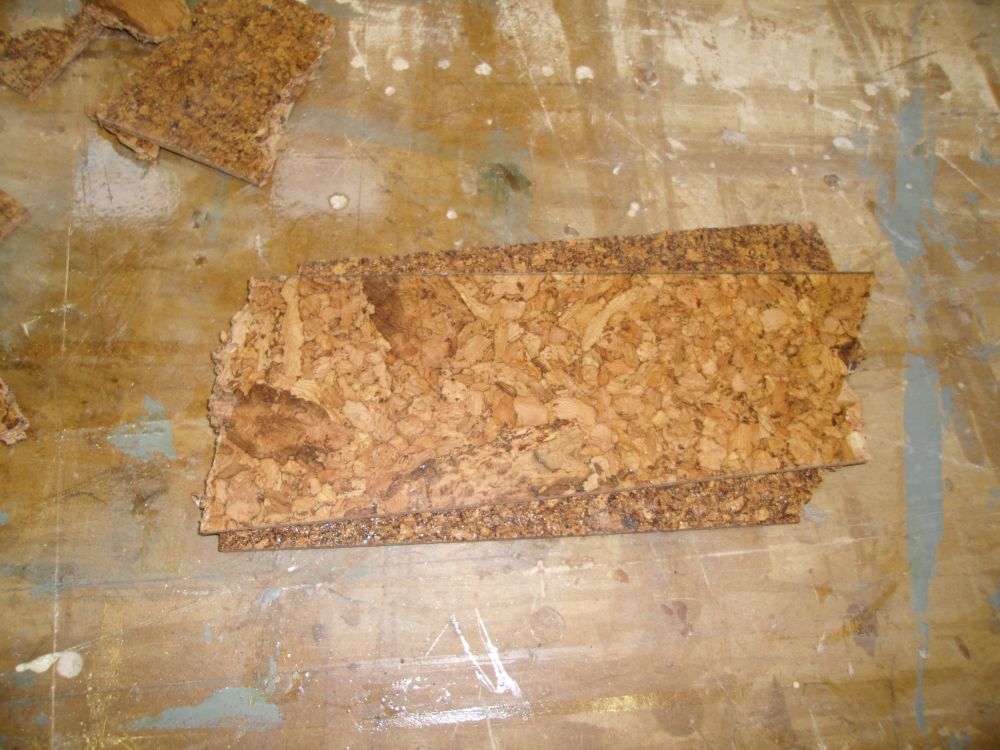
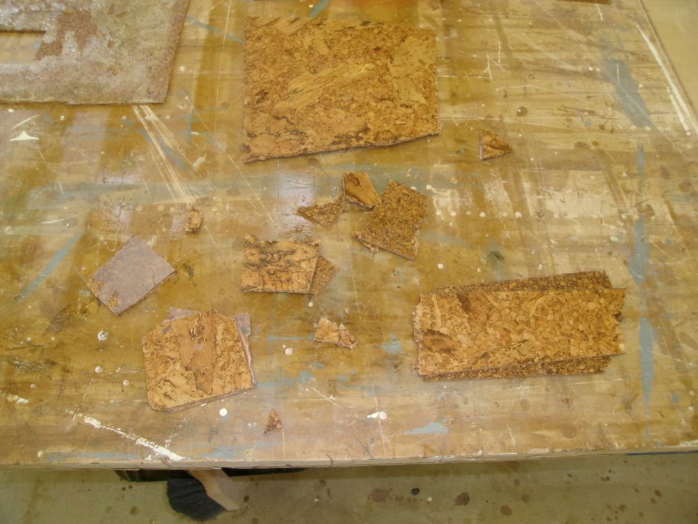
During the day, I continued various tests with some scrap cork pieces and solvent-based products to try and create a damaging issue--or, hopefully, not. So far, all tests had failed to destroy the cork, despite heavy applications of solvent-based contact cement and epoxy. Bonding between two pieces of contact cement-coated cork seemed strong and unbreakable. These photos don't show much, other than rough and broken cork bits, but I could determine no difference in the friability of the solvent-treated cork vs. the untouched new cork.
Total Time on This Job Today: 8 hours